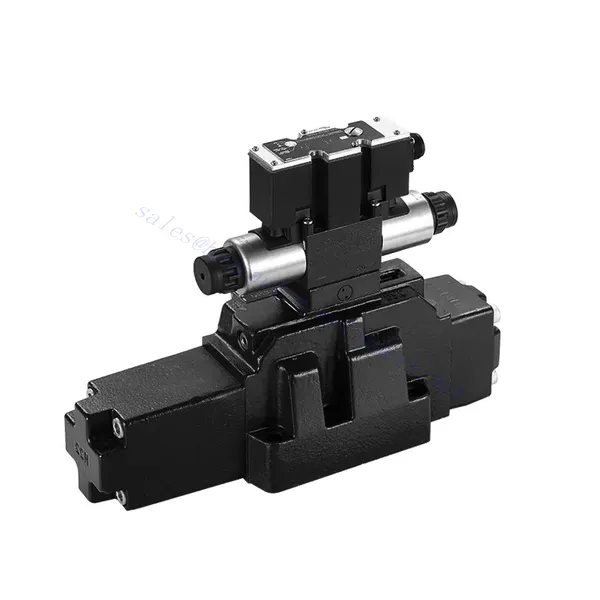
4WRZ/H(E) Series Pilot Operated Proportional Directional Hydraulic Valve
Como um dos fabricantes, fornecedores e exportadores de produtos mecânicos de cilindros hidráulicos, oferecemos cilindros hidráulicos e muitos outros produtos.
Entre em contato conosco para obter detalhes.
Correio eletrônico:sales@hydraulic-cylinders.net
Fabricante, fornecedor e exportador de cilindros hidráulicos.
4WRZ/H(E) Series Pilot Operated Proportional Directional Hydraulic Valve
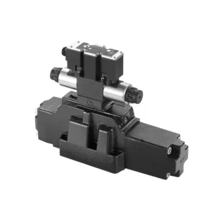
The 4WRZ/H(E) series pilot-operated proportional directional hydraulic valve is a state-of-the-art component designed to provide exceptional precision, control, and efficiency in hydraulic systems. With its advanced pilot-operated proportional control technology, this valve enables accurate flow regulation and seamless directional changes.
The 4WRZ/H(E) series pilot-operated proportional directional hydraulic valve empowers hydraulic systems with precise flow control, versatile directional changes, and energy efficiency. Its pilot-operated proportional control technology ensures accurate and responsive flow adjustment, while the high flow capacity guarantees reliable performance even in demanding applications. By following the recommended usage methods and maintenance guidelines, you can maximize the benefits and longevity of the 4WRZ/H(E) series valve, elevating your hydraulic system to new levels of precision and control. Upgrade your hydraulic setup today and experience the power of the 4WRZ/H(E) series pilot-operated proportional directional hydraulic valve.
4WRZ/H(E) Series Pilot Operated Proportional Directional Hydraulic Valve Key Characteristics:
- Pilot-Operated Proportional Control
- The 4WRZ/H(E) series valve utilizes pilot-operated proportional control technology, allowing precise and proportional flow adjustment based on control signals.
- This feature ensures accurate and responsive control, resulting in improved system performance, reduced energy consumption, and enhanced productivity.
- Versatile Directional Control
- This valve offers versatile control over hydraulic fluid direction, making it suitable for a wide range of applications.
- It enables seamless activation and deactivation of hydraulic components such as cylinders, motors, and actuators in different directions, enhancing system flexibility and adaptability.
- High Flow Capacity
- The 4WRZ/H(E) series valve is engineered to handle high flow rates, making it ideal for applications that require substantial hydraulic power.
- Its robust construction ensures reliable performance even under demanding conditions, providing consistent and efficient flow control.
- Energy Efficiency
- By incorporating pilot-operated proportional control, this valve minimizes pressure drops and optimizes energy usage.
- It helps reduce energy consumption, resulting in cost savings and environmental benefits.
4WRZ/H(E) Series Pilot Operated Proportional Directional Hydraulic Valve Parameter:
| GeneraL | |||||||
| Valve type | WRZ | WRZE | |||||
| Installation | Optional,preferably horizontal | ||||||
| Storage temperature range | ℃ | -20 to +80 | |||||
| Ambient temperature range | ℃ | -20 to +70 | -20 to +50 | ||||
| Weight | NS 10 | kg | 7.8 | 8 | |||
| NS 16 | kg | 13.4 | 13.6 | ||||
| NS 25 | kg | 18.2 | 18.4 | ||||
| NS 32 | kg | 42.2 | 42.4 | ||||
| Hydraulic (measured with HLPAG.p=100bar : 40 ℃ ± 5 ℃) | |||||||
| Size | 10 | 16 | 25 | 32 | |||
| Operating pressure | Pilot valve | External pilot oil supply | bar | 30 to 100 bar | |||
| Internal pilot oil supply | bar | 100 to 350 with “D3” only | |||||
| Main valve | bar | to 315 | to 350 | to 350 | to 350 | ||
| Return pressure | Port T (Port R) (external pilot oil drain)) | bar | to 315 | to 250 | to 250 | to 150 | |
| Port T (internal pilot oil drain) | bar | to 30 | to 30 | to 30 | to 30 | ||
| Port Y | bar | to 30 | to 30 | to 30 | to 30 | ||
| Pilot oil volume input signal 0- 100 % | cm3 | 1.7 | 4.6 | 10 | 26.5 | ||
| Pilot oil flow in port X and Y with a stepped input signal 0- 100 % | 3.5 | 5.5 | 7 | 15.9 | |||
| Flow of the main valve | L/min | to 170 | to 460 | to 870 | to 1600 | ||
| Hydraulic fluid | L/min | Mineral oil (HL, HLP) to DIN 51524 Further fluids on enquiry | |||||
| Hydraulic fluid temperature range | ℃ | -20 to +80(preferably +40 to +50) | |||||
| Viscosity range | mm2/s | 20 to 380(preferably 30 to 46) | |||||
| Degree of contamination | Maximum permissible degree of contamination of the pressure fluid is to NAS 1638 or ISO 4406(c) | A filter with a minimum retention rate of βx ≥ 75 is recommended | |||||
| Pilot valve | NAS 1638 class 7 | x=5 | |||||
| Main valve | NAS 1638 class 9 | x=15 | |||||
| Hysteresis | % | ≤6 | |||||
| Electrical | |||||||
| Valve type | WRZ | WRZE | |||||
| Type of protection of the valve to EN 60529 | IP65 with cable socket mounted and locked | ||||||
| Voltage type | DC | ||||||
| Command value overlap | % | 15 | |||||
| Max. current | A | 1.5 | 2.5 | ||||
| Solenoid coil resisance | Cold value at 20℃ | Ω | 4.8 | 2 | |||
| Max. warm value | Ω | 7.2 | 3 | ||||
| Cyclic duration factor | % | 100 | |||||
| Coil temperature | ℃ | to 150 | |||||
| Valve protection to EN 60529 | IP65 | ||||||
| Control electronics | |||||||
| External amplifier for type WRZ | VT- VSPA2-L2X/… | ||||||
| Command value signal | -Voltage input “A1” | V | ±10 | ||||
| –Current input “F1” | mA | 4 to 20 | |||||
4WRZ/H(E) Series Pilot Operated Proportional Directional Hydraulic Valve Advantages:
• Pilot-operated two-stage proportional directional valve, used to control the size and direction of the liquid flow
• Threaded connection type proportional solenoid, the coil can be disassembled separately
• Sub-plate mounting connection structure, connection size conforms to DIN2430 and ISO4401 standards
• Spool spring alignment alignment
• WRZE type with integrated proportional amplifierr
• WRZ type external amplifier (order separately)
Usage Method Of 4WRZ/H(E) Series Pilot Operated Proportional Directional Hydraulic Valve:
- System Evaluation
- Evaluate your hydraulic system and identify the specific flow and directional control requirements.
- Determine if the 4WRZ/H(E) series valve is suitable based on its flow capacity, pressure rating, and compatibility with your system.
- Valve Selection
- Select the appropriate variant of the 4WRZ/H(E) series valve based on your system parameters, flow requirements, and directional control needs.
- Consider factors such as maximum flow rate, pressure rating, response time, and operational conditions.
- Installation
- Follow the manufacturer’s installation instructions carefully, ensuring proper alignment and secure mounting of the valve.
- Make leak-free connections and ensure the correct flow direction alignment to guarantee optimal performance.
- Control Signal Connection
- Connect the control signal wires of the valve to a suitable control device, such as a proportional amplifier or electronic control unit.
- Ensure proper wiring and compatibility between the valve and the control device for accurate and responsive control.
How To Bleed Hydraulic Control Valve?
Bleeding a hydraulic control valve is an essential maintenance procedure to remove any trapped air or gas from the system, ensuring optimal performance and efficiency. Here’s a step-by-step guide on how to bleed a hydraulic control valve:
- Prepare the System:
- Ensure that the hydraulic system is turned off and that the pressure is relieved. This step is crucial for your safety and to prevent any accidental movement or release of high-pressure fluids.
- Locate the bleeder valve or bleed screw on the hydraulic control valve. It is typically located on the top or side of the valve body and may have a protective cap or cover.
- Positioning and Safety Measures:
- Place a suitable container or absorbent material beneath the bleed valve to catch any fluid that may be expelled during the bleeding process.
- Wear appropriate personal protective equipment (PPE), such as safety goggles and gloves, to protect yourself from hydraulic fluid splashes.
- Opening the Bleed Valve:
- Using an appropriate wrench or tool, carefully loosen the bleed valve or screw counterclockwise. Be cautious not to fully remove it at this stage.
- The bleed valve may have an O-ring or sealing washer. Take note of its position and ensure it is in good condition.
- System Activation:
- Activate the hydraulic system by turning on the power source, such as an engine or hydraulic pump.
- Operate the control mechanism associated with the hydraulic control valve, such as a joystick or lever, to allow fluid flow through the valve.
- Bleeding Process:
- Slowly open the bleed valve by turning it counterclockwise until you start to see hydraulic fluid or air bubbles escaping from the valve.
- Allow the fluid to flow for a few seconds or until you observe a steady stream of fluid without any air bubbles. This indicates that the air has been purged from the system.
- Be cautious not to open the bleed valve too much, as it may lead to excessive fluid loss or system damage.
- Closing the Bleed Valve:
- Once you have successfully bled the system, close the bleed valve by turning it clockwise. Ensure it is tightened securely but avoid over-tightening.
- Check for any leaks around the bleed valve or other connections. If you notice any leaks, address them promptly to prevent further issues.
- System Check:
- Turn off the hydraulic system and inspect the fluid level in the reservoir. Add hydraulic fluid as necessary to maintain the recommended level.
- Test the operation of the hydraulic control valve and associated components to ensure proper functionality.
Aptidão e capacidade da fábrica:
(1) Montagem
Temos uma plataforma de montagem de pesquisa e desenvolvimento independente de primeira classe. A oficina de produção de cilindros hidráulicos tem quatro linhas de montagem semiautomáticas de cilindros de elevação e uma linha de montagem automática de cilindros de inclinação, com uma capacidade de produção anual projetada de 1 milhão de peças. A oficina de cilindros especiais é equipada com várias especificações de um sistema de montagem de limpeza semiautomática com uma capacidade de produção anual projetada de 200.000 peças e equipada com famosos equipamentos de usinagem CNC, um centro de usinagem, um equipamento especial de processamento de cilindros de alta precisão, uma máquina de solda robotizada, uma máquina de limpeza automática, uma máquina de montagem automática de cilindros e uma linha de produção de pintura automática. O equipamento crítico existente é de mais de 300 conjuntos (conjuntos). A alocação ideal e o uso eficiente dos recursos do equipamento garantem os requisitos de precisão dos produtos e atendem às necessidades de alta qualidade dos produtos.


(2) Usinagem
A oficina de usinagem é equipada com um centro de torneamento de trilho inclinado personalizado, um centro de usinagem, uma máquina de brunimento de alta velocidade, um robô de soldagem e outros equipamentos relacionados, que podem lidar com o processamento de tubos de cilindros com diâmetro interno máximo de 400 mm e comprimento máximo de 6 metros.

(3) Soldagem

(4) Pintura e revestimento
Com linhas de revestimento de tinta à base de água automáticas de cilindros de pequeno e médio porte, para obter carregamento e descarregamento automáticos de robôs e pulverização automática, a capacidade projetada é de 4.000 peças por turno;
Também temos uma linha de produção de tinta semiautomática para cilindros grandes, acionada por uma corrente elétrica, com capacidade de projeto de 60 caixas por turno.


(5) Testes
Temos instalações de inspeção e bancos de teste de primeira classe para garantir que o desempenho do cilindro atenda aos requisitos.

We are one of the best hydraulic cylinder manufacturers. We can offer comprehensive hydraulic cylinders. We also provide corresponding caixas de câmbio agrícolas. Exportamos nossos produtos para clientes em todo o mundo e conquistamos uma boa reputação devido à qualidade superior de nossos produtos e ao serviço pós-venda. Convidamos clientes nacionais e estrangeiros a entrar em contato conosco para negociar negócios, trocar informações e cooperar conosco!
Faça um tour pela nossa fábrica de RV:
Faça um tour pela nossa fábrica de RV com o seguinte
Cilindro hidráulico Aplicação:
