


Válvulas hidráulicas direcionais da série WEH operadas por piloto
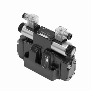

The WEH series directional hydraulic valves of pilot operated are advanced components that provide precise and efficient control over hydraulic systems. Designed to meet the demands of various industries, these valves offer exceptional performance, reliability, and versatility.
The WEH series directional hydraulic valves of pilot operated are reliable, high-performance components that empower operators with precise control and efficient fluid management in hydraulic systems. With their pilot-operated design, exceptional directional control, a wide range of configurations, and high flow capacity, these valves offer the reliability and versatility required in various industries. Following the recommended usage methods and adhering to regular maintenance practices, the WEH series valves will continue delivering exceptional performance. Upgrade your hydraulic system with the WEH series directional hydraulic valves operated and experience the benefits of precision, control, and reliability.
WEH Series Directional Hydraulic Valves Of Pilot Operated Key Characteristics:
- Projeto operado por piloto:
- The WEH series valves utilize a pilot-operated design, which enhances their responsiveness and control accuracy.
- This design enables the valves to handle high-pressure applications, ensuring optimal performance easily.
- Controle direcional:
- These hydraulic valves excel in providing precise directional control of hydraulic fluid.
- Operators can easily manage fluid flow and direct it to different actuators or components within the hydraulic system.
- Wide Range of Configurations:
- The WEH series valves are available in various configurations, including various sizes, flow rates, and pressure ratings.
- This versatility allows them to be tailored to specific application requirements and system specifications.
- Alta capacidade de fluxo:
- These valves are designed to handle high flow rates, making them suitable for applications that demand substantial fluid flow.
- Their optimized internal passages and robust construction ensure minimal pressure drop and efficient fluid management.
WEH Series Directional Hydraulic Valves Of Pilot Operated Parameter:
NG10
| Especificações | WEH10 type | |||||||||
| Max. operating pressure:P、A、B | 350 | |||||||||
| Porto T | Com barra de drenagem de óleo piloto externa | 315 | ||||||||
| Com barra interna de drenagem de óleo piloto | DC 210 AC 160 | |||||||||
| Porto Y | Com barra de drenagem de óleo piloto externa | DC 210 AC 160 | ||||||||
| Pressão mínima de controle | With external pilot oil supply ( not apply to C、Z、 F、G、H、P、T、V) bar |
3-position valve 10 | ||||||||
| Spring-return 2-position valve 10 | ||||||||||
| Hydraulic-return 2-position valve 7 | ||||||||||
| With internal pilot oil supply ( apply to C、Z、F、 G、H、P、T、V) bar |
6.5 | |||||||||
| barra de pressão máxima de controle | 250 | |||||||||
| Fluido | Óleo mineral, éster de fosfato | |||||||||
| Faixa de temperatura do fluido ℃ | -30 a +80 (vedações NBR) | |||||||||
| -20 a +80 (selos FKM) | ||||||||||
| Viscosity range mm2/s | 2,8 a 500 | |||||||||
| Switching pilot oil volume cm3 | 3-position valve 2.04 | |||||||||
| 2-position valve 4.08 | ||||||||||
| Switching times (= Valve switching time from the neutral position to the switched position)(AC and DC ) | ||||||||||
| Barra de pressão de controle | 70 | 140 | 210 | 250 | ||||||
| AC | DC | AC | DC | AC | DC | AC | DC | |||
| 3-position valve ms | 30 | 65 | 25 | 60 | 20 | 55 | 15 | 50 | ||
| 2-position valve ms | 35 | 80 | 30 | 75 | 25 | 70 | 20 | 65 | ||
| Tempos de comutação (= Tempo de comutação da válvula da posição comutada para a posição neutra) | ||||||||||
| 3-position valve ms | 30 | |||||||||
| 2-position valve ms | 35 | 40 | 30 | 35 | 25 | 30 | 20 | 25 | ||
| Posição de instalação | HC、HD、HK、HZ、HY Type hydraulic-return valves are installed horizontally, the rest can be installed arbitrarily | |||||||||
| Flow of shortest switching time L/min | cerca de 35 | |||||||||
| Peso | Single solenoid valve kg | 6.7 | ||||||||
| Double solenoid valve kg | 7.1 | |||||||||
| Switching time regulator kg | 1.0 | |||||||||
| Reducing valve kg | 0.5 | |||||||||
NG16
| Especificações | WEH16… type | |||||||||||||
| Max. operating pressure:P、A、B | 350 | |||||||||||||
| Porto T | Com barra de drenagem de óleo piloto externa | 250 | ||||||||||||
| Com barra interna de drenagem de óleo piloto | DC 210 AC 160 | |||||||||||||
| Porto Y | Com barra de drenagem de óleo piloto externa | DC 210 AC 160 | ||||||||||||
| Pressão mínima de controle | With external pilot oil supply ( not apply to C、Z、 F、G、H、P、T、V)bar |
3-position valve 14 | ||||||||||||
| Válvula de 2 posições com retorno por mola 14 | ||||||||||||||
| Hydraulic-return 2-position valve 14 | ||||||||||||||
| With internal pilot oil supply ( apply to C、Z、F、 G、 H、P、T、V) bar |
When applying prepressing or the flow is large correspondingly ,enginery of spool valve is 4.5 as C,Z,F,G,H,P,T and V | |||||||||||||
| barra de pressão máxima de controle | 250 | |||||||||||||
| Fluido | Óleo mineral, éster de fosfato | |||||||||||||
| Faixa de temperatura do fluido ℃ | -30 a +80 (vedações NBR) | |||||||||||||
| -20 a +80 (selos FKM) | ||||||||||||||
| Viscosity range mm2/s | 2,8 a 500 | |||||||||||||
| Comutação do volume de óleo piloto | ||||||||||||||
| – Spring-centering 3-position valve cm3 | 5.72 | |||||||||||||
| – 2-position valve cm3 | 11.45 | |||||||||||||
| * * Switching times (= Valve switching time from the neutral position to the switched position)(AC and DC) | ||||||||||||||
| Barra de pressão de controle | 50 | 150 | 250 | |||||||||||
| AC | DC | AC | DC | AC | DC | AC | DC | AC | DC | AC | DC | |||
| – Spring-centering 3-position valve ms | 35 | 65 | 30 | 60 | 30 | 58 | ||||||||
| – 2-position valve ms | 45 | 65 | 35 | 55 | 30 | 50 | ||||||||
| **Tempos de comutação (= Tempo de comutação da válvula da posição neutra para a posição comutada) | ||||||||||||||
| – Spring-centering 3-position valve ms | 30 | |||||||||||||
| – 2-position valve ms | 45 | 45 | 35 | 35 | 30 | 30 | ||||||||
| Posição de instalação | C,D,K,Z,Y Type hydraulic-return valves are installed horizontally, the rest can be installed arbitrarily | |||||||||||||
| Flow of shortest switching time L/min | cerca de 35 | |||||||||||||
| Weight kg | about 9.5 | |||||||||||||
NG25
| Especificações | WEH25… type | |||||||||||||||||
| Max. operating pressure:P、A、B | 350 | |||||||||||||||||
| Porto T | Com barra de drenagem de óleo piloto externa | 250 | ||||||||||||||||
| Com barra interna de drenagem de óleo piloto | DC 210 AC 160 | |||||||||||||||||
| Porto Y | Com barra de drenagem de óleo piloto externa | DC 210 AC 160 | ||||||||||||||||
| Pressão mínima de controle | With external pilot oil supply ( not apply to C、Z、F、 G、H、P、T、V) bar |
Spring-centering 3-position valve 13 | ||||||||||||||||
| Spring-return 2-position valve 13 | ||||||||||||||||||
| Hydraulic-return 2-position valve 8 | ||||||||||||||||||
| With internal pilot oil supply ( apply to C、Z、F、 G、H、P、T、V) bar |
When applying prepressing or the flow is large correspondingly ,enginery of spool valve is 4.5 as C,Z,F,G,H,P,T and V | |||||||||||||||||
| barra de pressão máxima de controle | 250 | |||||||||||||||||
| Fluido | Óleo mineral, éster de fosfato | |||||||||||||||||
| Faixa de temperatura do fluido ℃ | -30 a +80 (vedações NBR) | |||||||||||||||||
| -20 a +80 (selos FKM) | ||||||||||||||||||
| Comutação do volume de óleo piloto | ||||||||||||||||||
| – Spring-centering 3-position valve cm3 | 14.2 | |||||||||||||||||
| – 2-position valve cm3 | 28.4 | |||||||||||||||||
| * Tempos de comutação (= Tempo de comutação da válvula da posição neutra para a posição comutada) (CA e CC) | ||||||||||||||||||
| Barra de pressão de controle | 50 | 140 | 210 | 250 | ||||||||||||||
| AC | DC | AC | DC | AC | DC | AC | DC | |||||||||||
| – Spring-centering 3-position valve ms | 50 | 85 | 40 | 75 | 35 | 70 | 30 | 65 | ||||||||||
| – 2-position valve ms | 120 | 160 | 100 | 130 | 85 | 120 | 70 | 105 | ||||||||||
| *Tempos de comutação (= Tempo de comutação da válvula da posição neutra para a posição comutada) | ||||||||||||||||||
| – Spring-centering 3-position valve ms | 40 | |||||||||||||||||
| – 2-position valve ms | 120 | 125 | 95 | 100 | 85 | 90 | 75 | 80 | ||||||||||
| Posição de instalação | C,D,K,Z,Y Type hydraulic-return valves are installed horizontally, the rest can be installed arbitrarily | |||||||||||||||||
| Flow of shortest switching time L/min | cerca de 35 | |||||||||||||||||
| Weight kg | about 18 | |||||||||||||||||
NG32
| Especificações | WEH32… type | |||||||||||||
| Max. operating pressure:P、A、B | 350 | |||||||||||||
| Porto T | Com barra de drenagem de óleo piloto externa | 250 | ||||||||||||
| Com barra interna de drenagem de óleo piloto | DC 210 AC 160 | |||||||||||||
| Porto Y | Com barra de drenagem de óleo piloto externa | DC 210 AC 160 | ||||||||||||
| Pressão mínima de controle | Com fornecimento externo de óleo piloto
Com fornecimento interno de óleo piloto |
3-position valve 8.5 | ||||||||||||
| Spring-return 2-position valve 10 | ||||||||||||||
| Hydraulic-return 2-position valve 15 | ||||||||||||||
| With internal pilot oil supply ( apply to C、Z、F、 G、H、P、T、V) bar |
When applying prepressing or the flow is large correspondingly ,enginery of spool valve is 4.5 as C,Z,F,G,H,P,T and V | |||||||||||||
| barra de pressão máxima de controle | 250 | |||||||||||||
| Fluido | Óleo mineral, éster de fosfato | |||||||||||||
| Faixa de temperatura do fluido ℃ | -30 a +80 (vedações NBR) | |||||||||||||
| -20 a +80 (selos FKM) | ||||||||||||||
| Viscosity range mm2/s | 2,8 a 500 | |||||||||||||
| Comutação do volume de óleo piloto | ||||||||||||||
| – Spring-centering 3-position valve cm3 | 29.4 | |||||||||||||
| – 2-position valve cm3 | 58.8 | |||||||||||||
| * Tempos de comutação (= Tempo de comutação da válvula da posição neutra para a posição comutada) (CA e CC) | ||||||||||||||
| Barra de pressão de controle | 50 | 150 | 250 | |||||||||||
| AC | DC | AC | DC | AC | DC | |||||||||
| – Spring-centering 3-position valve ms | 65 | 80 | 50 | 90 | 35 | 105 | ||||||||
| – 2-position valve ms | 100 | 130 | 75 | 100 | 60 | 115 | ||||||||
| *Tempos de comutação (= Tempo de comutação da válvula da posição neutra para a posição comutada) | ||||||||||||||
| – Spring-centering 3-position valve ms | ( DC :50,AC :60) | |||||||||||||
| – 2-position valve ms | 115 | 90 | 35 | 70 | 65 | 65 | ||||||||
| Posição de instalação | C、D、K、Z、YType hydraulic-return valves are installed horizontally, the rest can be installed arbitrarily | |||||||||||||
| Flow of shortest switching time L/min | about 50 | |||||||||||||
| Weight kg | about 36 | |||||||||||||
WEH Series Directional Hydraulic Valves Of Pilot Operated Advantages:
• Electrohydraulic directioanl valve directioanls the oil path by controlling the main spool
• Controle eletro-hidráulico WEH
• Installation face follow DIN 24340 A, ISO 4401 and CETOP-RP 121H Sub-plate mounting connection
• Wet DC or AC solenoid (optional)
• Com controle manual de emergência
• Electropneumatic connection as single or center connection
• Spring or hydraulic alignment or bias
Usage Method Of WEH Series Directional Hydraulic Valves Of Pilot Operated:
- Integração de sistemas:
- Identify the optimal location for installing the WEH series valves within the hydraulic system, considering the desired flow path and control requirements.
- Ensure compatibility with the system’s pressure and flow specifications.
- Fixe as válvulas de forma segura utilizando suportes ou acessórios de montagem apropriados.
- Pilot Control Setup:
- Connect the pilot control lines to the designated ports on the valves, following the manufacturer’s instructions.
- Ensure proper sizing and routing of the pilot lines to maintain optimal control signal integrity.
- Conexões de fluidos:
- Selecione conexões hidráulicas e mangueiras compatíveis para conexões seguras e sem vazamentos.
- Follow the manufacturer’s instructions for proper torque values during the installation process.
- Use selantes de rosca ou fita apropriados para garantir vedações confiáveis.
- Controle e Ajuste:
- To operate the WEH series valves, utilize the recommended control method, such as manual levers or electrical controls.
- Adjust the valves’ settings to achieve the desired flow direction and rates, ensuring optimal performance.
How Do Hydraulic Valve Lifters Work?
Hydraulic valve lifters, also known as hydraulic tappets or hydraulic lash adjusters, play a vital role in the proper operation of an internal combustion engine. They are responsible for maintaining the proper clearance, or “lash,” between the engine’s camshaft and valve train components. Here’s an overview of how hydraulic valve lifters work:
- Structure:
- Hydraulic valve lifters are small cylindrical devices typically made of metal.
- They are between the camshaft and the engine’s valve train components, such as the pushrods, rocker arms, or overhead cam followers.
- Hydraulic Operation:
- Inside the hydraulic valve lifter, a small piston mechanism operates based on hydraulic pressure.
- The lifter is filled with hydraulic fluid, typically engine oil, which acts as a working fluid.
- Camshaft Interaction:
- The camshaft has lobes or eccentric shapes that push against the lifters as it rotates.
- As the camshaft lobe comes into contact with the lifter, it applies a force that compresses its internal piston.
- Lash Adjustment:
- When the lifter’s piston is compressed, it pushes the hydraulic fluid out of the lifter through a small orifice.
- This hydraulic fluid is expelled into the engine’s oil galleries or passages.
- Lash Compensation:
- The expelled hydraulic fluid creates a hydraulic cushion or “spring” effect, compensating for any clearance or lash between the camshaft lobe and the valve train components.
- This compensation eliminates excessive clearance and ensures that the valve train remains in constant contact with the camshaft lobes.
- Maintenance of Lash:
- If there is excessive clearance or lash in the valve train due to wear or other factors, the lifter’s internal piston will extend further to maintain the necessary hydraulic pressure.
- This extended position allows the lifter to take up the additional clearance, thus maintaining proper valve lash.
- Oil Pressure and Lubrication:
- The hydraulic valve lifters rely on the engine’s oil pressure for proper operation.
- The oil pump circulates oil through the engine, and the lifters receive a continuous oil supply to maintain hydraulic pressure and lubrication.
Aptidão e capacidade da fábrica:
(1) Montagem
Temos uma plataforma de montagem de pesquisa e desenvolvimento independente de primeira classe. A oficina de produção de cilindros hidráulicos tem quatro linhas de montagem semiautomáticas de cilindros de elevação e uma linha de montagem automática de cilindros de inclinação, com uma capacidade de produção anual projetada de 1 milhão de peças. A oficina de cilindros especiais é equipada com várias especificações de um sistema de montagem de limpeza semiautomática com uma capacidade de produção anual projetada de 200.000 peças e equipada com famosos equipamentos de usinagem CNC, um centro de usinagem, um equipamento especial de processamento de cilindros de alta precisão, uma máquina de solda robotizada, uma máquina de limpeza automática, uma máquina de montagem automática de cilindros e uma linha de produção de pintura automática. O equipamento crítico existente é de mais de 300 conjuntos (conjuntos). A alocação ideal e o uso eficiente dos recursos do equipamento garantem os requisitos de precisão dos produtos e atendem às necessidades de alta qualidade dos produtos.


(2) Usinagem
A oficina de usinagem é equipada com um centro de torneamento de trilho inclinado personalizado, um centro de usinagem, uma máquina de brunimento de alta velocidade, um robô de soldagem e outros equipamentos relacionados, que podem lidar com o processamento de tubos de cilindros com diâmetro interno máximo de 400 mm e comprimento máximo de 6 metros.


(3) Soldagem


(4) Pintura e revestimento
Com linhas de revestimento de tinta à base de água automáticas de cilindros de pequeno e médio porte, para obter carregamento e descarregamento automáticos de robôs e pulverização automática, a capacidade projetada é de 4.000 peças por turno;
Também temos uma linha de produção de tinta semiautomática para cilindros grandes, acionada por uma corrente elétrica, com capacidade de projeto de 60 caixas por turno.


(5) Testes
Temos instalações de inspeção e bancos de teste de primeira classe para garantir que o desempenho do cilindro atenda aos requisitos.


Somos um dos melhores fabricantes de cilindros hidráulicos. Oferecemos cilindros hidráulicos completos. Também fornecemos os correspondentes caixas de câmbio agrícolas. Exportamos nossos produtos para clientes em todo o mundo e conquistamos uma boa reputação devido à qualidade superior de nossos produtos e ao serviço pós-venda. Convidamos clientes nacionais e estrangeiros a entrar em contato conosco para negociar negócios, trocar informações e cooperar conosco!