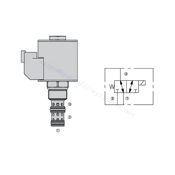
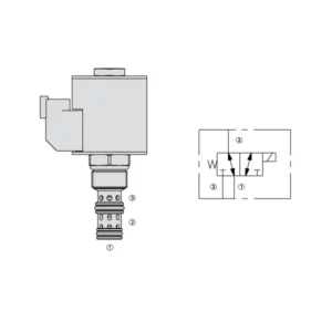
30SD10-34 Solenoid Directional Valve
Como um dos fabricantes, fornecedores e exportadores de produtos mecânicos de cilindros hidráulicos, oferecemos cilindros hidráulicos e muitos outros produtos.
Entre em contato conosco para obter detalhes.
Correio eletrônico:sales@hydraulic-cylinders.net
Fabricante, fornecedor e exportador de cilindros hidráulicos.
30SD10-34 Solenoid Directional Valve
The 30SD10-34 solenoid directional valve is a cutting-edge industrial component designed to provide precise and reliable fluid control in a wide range of applications. With its advanced features, durable construction, and user-friendly design, this solenoid directional valve offers enhanced performance and efficiency.
The 30SD10-34 solenoid directional valve is a reliable and versatile component that offers precise fluid control in industrial applications. Its robust construction, precision control, and reliable performance make it an ideal choice for enhancing the efficiency and productivity of your fluid control systems. By following the recommended usage methods and maintenance guidelines, you can ensure optimal performance and longevity of the 30SD10-34 solenoid directional valve in your industrial operations.
30SD10-34 Solenoid Directional Valve Characteristics:
- Robust Construction: The 30SD10-34 solenoid directional valve is built with high-quality materials and meticulous craftsmanship, ensuring durability and longevity. Its robust construction allows it to withstand demanding industrial environments, providing reliable performance even under harsh conditions.
- Versatile Functionality: This solenoid directional valve offers versatile functionality, making it suitable for various applications. It effectively controls the direction of fluid flow, allowing precise and efficient operation in different industrial systems.
- Precision Control: With exceptional precision, the 30SD10-34 solenoid directional valve enables accurate control over fluid flow. It allows for precise regulation and adjustment of fluid direction and pressure, ensuring optimal performance and efficiency in industrial processes.
- Reliable Performance: This solenoid directional valve delivers reliable performance, minimizing the risk of system failures or interruptions. It operates dependably, contributing to increased productivity and reduced downtime in industrial operations.
30SD10-34 Solenoid Directional Valve Parameter:
| Pressão nominal | 207 bar (3000 psi) | |
| Proof pressure | 350 bar (5075 psi) | |
| Pico de fluxo | 22.7 L/min (6 gpm) | |
| Fluido | À base de minerais ou sintéticos com propriedades lubrificantes | |
| Faixa de temperatura ℃ | -54 a 107 ℃ (Vedantes de poliuretano) | |
| -40 a 100 ℃ (vedações Buna N) | ||
| -26 a 204 ℃ (vedações de fluorocarbono) | ||
| Faixa de viscosidade | 7,4 a 420 mm2/s | |
| Grau de contaminação | O nível mínimo de poluição é ISO4406 nível 20/18/14, e o nível 17/15/13 é recomendado para prolongar a vida útil | |
| Vazamento interno | ≤ 115 mL/min@207bar | |
| Cavidade | VC10-3 | |
| Classificação de serviço da bobina | Contínuo de 85% a 115% de tensão nominal | |
| Response time | First indication of change of state with 100% voltage supplied at80% of nominal flow rating:Energized: 60 msec. ; De-energized: 10 msec. | |
| Consumo inicial de corrente da bobina a 20℃ | Bobina eletrônica | 1,7 A a 12 VCC; 0,85 A a 24 VCC |
| Bobina D | 1,67 A a 12 VCC; 0,83 A a 24 VCC | |
| Tensão mínima de entrada | 85% de nominal a 207 bar | |
30SD10-34 Solenoid Directional Valve Advantages:
• Bobina nominal para serviço contínuo
• Construção eficiente de armadura úmida
• Os cartuchos são intercambiáveis em termos de voltagem
• Bobinas elétricas à prova d'água opcionais com classificação até IP69K
• All ports may be fully pressurized
• Cavidade comum da indústria
• Peças temperadas para longa vida útil e baixo vazamento
Usage Method Of 30SD10-34 Solenoid Directional Valve:
- Integration into System: Integrate the 30SD10-34 solenoid directional valve into the fluid control system following the manufacturer’s guidelines and specifications. Ensure proper alignment and connection between the valve and other system components to achieve optimal performance.
- Electrical Connection: Establish a secure electrical connection for the solenoid directional valve. Refer to the provided wiring diagram and ensure correct polarity to prevent any electrical malfunctions. Follow safety guidelines when working with electrical connections.
- Controle da direção do fluxo de fluido: Utilize a válvula direcional solenóide para controlar a direção do fluxo de fluido. A válvula geralmente é equipada com uma alavanca ou atuador para ajuste manual. Alternativamente, ela pode ser integrada a um sistema de controle automatizado para operação remota.
- Pressure Adjustment: Employ the solenoid directional valve to regulate fluid pressure within the system. By adjusting the valve’s settings, you can achieve the desired pressure levels for optimal performance and efficiency.
How To Plumb Auto Cycle Hydraulic Valve?
Plumbing an auto-cycle hydraulic valve requires careful attention to ensure proper installation and functionality. Follow these steps to plumb an auto-cycle hydraulic valve effectively:
- Reúna as ferramentas e materiais necessários: Before you begin, make sure you have all the required tools and materials, including hydraulic hoses, fittings, adapters, Teflon tape, wrenches, and a hydraulic fluid reservoir.
- Identify The Valve Ports: Examine the auto-cycle hydraulic valve to identify the different ports. Typically, there will be inlet ports, outlet ports, and possibly additional ports for pressure relief or auxiliary functions.
- Determine The Hydraulic Fluid Flow Direction: Determine the desired flow direction of the hydraulic fluid through the valve. This information is crucial for correctly connecting the inlet and outlet ports.
- Install Fittings And Adapters: Install the appropriate fittings and adapters onto the valve ports. Ensure they are tightened securely, but be careful not to overtighten and damage the threads.
- Apply Teflon Tape: Wrap Teflon tape around the threads of the fittings and adapters. This helps create a tight seal and prevents leaks.
- Connect Hydraulic Hoses: Attach hydraulic hoses to the fittings and adapters on the valve ports. Ensure the hoses are suitable for the hydraulic system’s pressure rating and are of the correct length.
- Secure Hose Connections: Use hose clamps or other suitable methods to secure the hydraulic hoses to the fittings. This prevents the hoses from coming loose during operation.
- Route The Hydraulic hoses: Carefully route the hydraulic hoses to connect the auto-cycle hydraulic valve to the hydraulic fluid reservoir and other hydraulic components, such as cylinders or motors. Avoid sharp bends or kinks in the hoses that could restrict fluid flow.
- Check For Leaks: Once all connections are made, check for leaks. Start by slowly pressurizing the system and inspecting each connection point. If you notice any leaks, tighten the fittings or replace faulty components as necessary.
- Fill The Hydraulic Fluid Reservoir: Fill the hydraulic fluid reservoir with the recommended type and quantity of hydraulic fluid. Refer to the manufacturer’s guidelines for the appropriate fluid specifications.
- Bleed Air From The System: B bleed any air trapped in the hydraulic system to ensure proper operation. Follow the manufacturer’s instructions for bleeding procedures, which typically involve cycling the design and opening bleed valves.
- Test The System: With the plumbing complete, test the auto-cycle hydraulic valve and the overall system’s performance. Verify that the valve functions as intended and that fluid flow is smooth and consistent.
Aptidão e capacidade da fábrica:
(1) Montagem
Temos uma plataforma de montagem de pesquisa e desenvolvimento independente de primeira classe. A oficina de produção de cilindros hidráulicos tem quatro linhas de montagem semiautomáticas de cilindros de elevação e uma linha de montagem automática de cilindros de inclinação, com uma capacidade de produção anual projetada de 1 milhão de peças. A oficina de cilindros especiais é equipada com várias especificações de um sistema de montagem de limpeza semiautomática com uma capacidade de produção anual projetada de 200.000 peças e equipada com famosos equipamentos de usinagem CNC, um centro de usinagem, um equipamento especial de processamento de cilindros de alta precisão, uma máquina de solda robotizada, uma máquina de limpeza automática, uma máquina de montagem automática de cilindros e uma linha de produção de pintura automática. O equipamento crítico existente é de mais de 300 conjuntos (conjuntos). A alocação ideal e o uso eficiente dos recursos do equipamento garantem os requisitos de precisão dos produtos e atendem às necessidades de alta qualidade dos produtos.


(2) Usinagem
A oficina de usinagem é equipada com um centro de torneamento de trilho inclinado personalizado, um centro de usinagem, uma máquina de brunimento de alta velocidade, um robô de soldagem e outros equipamentos relacionados, que podem lidar com o processamento de tubos de cilindros com diâmetro interno máximo de 400 mm e comprimento máximo de 6 metros.

(3) Soldagem

(4) Pintura e revestimento
Com linhas de revestimento de tinta à base de água automáticas de cilindros de pequeno e médio porte, para obter carregamento e descarregamento automáticos de robôs e pulverização automática, a capacidade projetada é de 4.000 peças por turno;
Também temos uma linha de produção de tinta semiautomática para cilindros grandes, acionada por uma corrente elétrica, com capacidade de projeto de 60 caixas por turno.


(5) Testes
Temos instalações de inspeção e bancos de teste de primeira classe para garantir que o desempenho do cilindro atenda aos requisitos.

Somos um dos melhores fabricantes de cilindros hidráulicos. Oferecemos cilindros hidráulicos completos. Também fornecemos os correspondentes caixas de câmbio agrícolas. Exportamos nossos produtos para clientes em todo o mundo e conquistamos uma boa reputação devido à qualidade superior de nossos produtos e ao serviço pós-venda. Convidamos clientes nacionais e estrangeiros a entrar em contato conosco para negociar negócios, trocar informações e cooperar conosco!
Cilindro hidráulico Aplicação:
