Válvula direcional solenóide 30SD10-40
Como um dos fabricantes, fornecedores e exportadores de produtos mecânicos de cilindros hidráulicos, oferecemos cilindros hidráulicos e muitos outros produtos.
Entre em contato conosco para obter detalhes.
Correio eletrônico:sales@hydraulic-cylinders.net
Fabricante, fornecedor e exportador de cilindros hidráulicos.
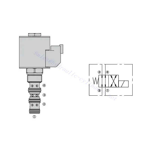
Válvula direcional solenóide 30SD10-40
A válvula direcional solenóide 30SD10-40 é um componente industrial de alto desempenho projetado para fornecer controle de fluidos preciso e confiável em diversas aplicações. Com seus recursos avançados, construção robusta e design intuitivo, esta válvula direcional solenóide oferece maior eficiência e confiabilidade operacional.
A válvula direcional solenóide 30SD10-40 é um componente confiável e versátil que oferece controle preciso de fluidos em aplicações industriais. Sua construção robusta, controle preciso e desempenho confiável aumentam a eficiência e a produtividade em sistemas de controle de fluidos. Seguindo os métodos de uso e as diretrizes de manutenção recomendadas, você pode garantir o desempenho ideal e a longa vida útil da válvula direcional solenóide 30SD10-40 em suas operações industriais.
Características da válvula direcional solenóide 30SD10-40:
- Construção Robusta: A válvula direcional solenóide 30SD10-40 é fabricada com excepcional precisão e materiais de alta qualidade, garantindo durabilidade e longa vida útil. Sua construção robusta permite que ela suporte ambientes industriais exigentes, proporcionando desempenho confiável mesmo em condições adversas.
- Funcionalidade versátil: Esta válvula direcional solenóide oferece funcionalidade versátil, tornando-a adequada para uma ampla gama de aplicações. Ela controla eficazmente a direção do fluxo de fluido, permitindo uma operação precisa e eficiente em diversos sistemas industriais.
- Controle de Precisão: A válvula direcional solenóide 30SD10-40 proporciona precisão excepcional no controle de fluidos. Ela permite a regulação e o ajuste precisos da direção e da pressão do fluido, garantindo desempenho e eficiência ideais em processos industriais.
- Desempenho confiável: Esta válvula direcional solenóide oferece desempenho confiável, minimizando o risco de falhas ou interrupções do sistema. Ela opera com segurança, contribuindo para o aumento da produtividade e a redução do tempo de inatividade em operações industriais.
Parâmetros da válvula direcional solenóide 30SD10-40:
| Pressão nominal | 207 bar (3000 psi) | |
| Pico de fluxo | 23 L/min (6 gpm) | |
| Fluido | À base de minerais ou sintéticos com propriedades lubrificantes | |
| Faixa de temperatura ℃ | -54 a 107 ℃ (Vedantes de poliuretano) | |
| -40 a 100 ℃ (vedações Buna N) | ||
| -26 a 204 ℃ (vedações de fluorocarbono) | ||
| Faixa de viscosidade | 7,4 a 420 mm2/s | |
| Grau de contaminação | O nível mínimo de poluição é ISO4406 nível 20/18/14, e o nível 17/15/13 é recomendado para prolongar a vida útil | |
| Vazamento interno | ≤ 82 mL/min a 207 bar | |
| Cavidade | VC10-4 | |
| Classificação de serviço da bobina | Contínuo de 85% a 115% de tensão nominal | |
| Consumo inicial de corrente da bobina a 20℃ | Bobina eletrônica | 1,7 A a 12 VCC; 0,85 A a 24 VCC |
| Bobina D | 1,67 A a 12 VCC; 0,83 A a 24 VCC | |
| Tensão mínima de entrada | 85% de nominal a 207 bar | |
Vantagens da válvula direcional solenóide 30SD10-40:
• Bobina nominal para serviço contínuo
• Os cartuchos são intercambiáveis em termos de voltagem
• Bobinas elétricas à prova d'água opcionais com classificação até IP69K
• Construção eficiente de armadura úmida
• Cavidade comum da indústria
• Peças temperadas para longa vida útil
Método de utilização da válvula direcional solenóide 30SD10-40 :
- Integration into the System: Integrate the 30SD10-40 Solenoid Directional Valve into the fluid control system following the manufacturer’s guidelines and specifications. Ensure proper alignment and connection between the valve and other system components to achieve optimal performance.
- Conexão elétrica: Estabeleça uma conexão elétrica segura para a válvula direcional solenóide. Siga o diagrama de fiação fornecido e assegure-se da polaridade correta para evitar mau funcionamento elétrico. Respeite as normas de segurança ao trabalhar com conexões elétricas.
- Controle da direção do fluxo de fluido: Utilize a válvula direcional solenóide para controlar a direção do fluxo de fluido. A válvula geralmente é equipada com uma alavanca ou atuador para ajuste manual. Alternativamente, ela pode ser integrada a um sistema de controle automatizado para operação remota.
- Pressure Adjustment: Use the solenoid directional valve to regulate fluid pressure within the system. Adjust the valve’s settings to achieve the desired pressure levels for optimal performance and efficiency.
Como ler diagramas de válvulas hidráulicas?
A leitura de diagramas de válvulas hidráulicas requer um conhecimento básico de símbolos hidráulicos e seus significados. Aqui estão os passos para ajudá-lo a ler diagramas de válvulas hidráulicas:
- Familiarize-se com os símbolos hidráulicos: Os diagramas hidráulicos utilizam símbolos gráficos para representar diversos componentes e funções. Os símbolos comuns incluem quadrados para válvulas, linhas para tubos ou mangueiras, setas para a direção do fluxo e círculos para dispositivos de controle de pressão ou vazão. Certifique-se de compreender o significado desses símbolos antes de prosseguir.
- Identifique os tipos de válvulas: Procure os símbolos das válvulas no diagrama. As válvulas podem ser representadas por quadrados com diferentes formatos e orientações. Por exemplo, um quadrado com uma linha diagonal representa uma válvula de retenção, enquanto um quadrado com uma seta dentro indica uma válvula direcional.
- Determine a função da válvula: Cada símbolo de válvula indica sua função específica. As válvulas direcionais determinam a direção do fluxo do fluido hidráulico, enquanto as válvulas de controle de pressão regulam os níveis de pressão. As válvulas de controle de fluxo gerenciam a vazão do fluido e as válvulas de retenção permitem o fluxo em apenas uma direção.
- Observe as conexões das válvulas: Preste atenção às linhas ou setas que entram e saem do símbolo da válvula. Essas linhas representam os caminhos do fluxo do fluido hidráulico. As setas indicam a direção do fluxo e as linhas que conectam as válvulas e outros componentes indicam as conexões.
- Analise as posições das válvulas: Alguns diagramas de válvulas hidráulicas incluem símbolos para ilustrar as posições da válvula. Esses símbolos geralmente representam o carretel ou a alavanca da válvula em diferentes posições, como aberta, fechada ou parcialmente aberta. Compreender as posições da válvula ajuda a determinar os caminhos do fluxo e o estado do sistema hidráulico.
- Considere símbolos e anotações adicionais: Os diagramas hidráulicos podem incluir símbolos e anotações adicionais para indicar manômetros, medidores de vazão, filtros, acumuladores ou outros componentes. Familiarize-se com esses símbolos e seus significados para obter uma compreensão completa do sistema.
- Siga os caminhos do fluxo: Descreva os caminhos do fluxo desde a fonte de energia hidráulica, passando pelas diversas válvulas e componentes, até o atuador ou a saída desejada. Compreenda como as válvulas interagem entre si e como controlam o fluxo, a pressão e a direção do fluido para alcançar o funcionamento desejado do sistema.
- Consulte a legenda ou o gabarito: O diagrama esquemático deve conter uma legenda ou chave que explique o significado de cada símbolo utilizado. Caso encontre símbolos desconhecidos ou tenha dúvidas sobre o seu significado, consulte a legenda para esclarecimentos.
- Busque recursos adicionais, se necessário: Se você precisar de uma compreensão mais aprofundada dos esquemas de válvulas hidráulicas, considere consultar livros didáticos de hidráulica, recursos online ou especialistas em hidráulica que possam fornecer orientações e explicações personalizadas para suas necessidades específicas.
Aptidão e capacidade da fábrica:
(1) Montagem
Temos uma plataforma de montagem de pesquisa e desenvolvimento independente de primeira classe. A oficina de produção de cilindros hidráulicos tem quatro linhas de montagem semiautomáticas de cilindros de elevação e uma linha de montagem automática de cilindros de inclinação, com uma capacidade de produção anual projetada de 1 milhão de peças. A oficina de cilindros especiais é equipada com várias especificações de um sistema de montagem de limpeza semiautomática com uma capacidade de produção anual projetada de 200.000 peças e equipada com famosos equipamentos de usinagem CNC, um centro de usinagem, um equipamento especial de processamento de cilindros de alta precisão, uma máquina de solda robotizada, uma máquina de limpeza automática, uma máquina de montagem automática de cilindros e uma linha de produção de pintura automática. O equipamento crítico existente é de mais de 300 conjuntos (conjuntos). A alocação ideal e o uso eficiente dos recursos do equipamento garantem os requisitos de precisão dos produtos e atendem às necessidades de alta qualidade dos produtos.


(2) Usinagem
A oficina de usinagem é equipada com um centro de torneamento de trilho inclinado personalizado, um centro de usinagem, uma máquina de brunimento de alta velocidade, um robô de soldagem e outros equipamentos relacionados, que podem lidar com o processamento de tubos de cilindros com diâmetro interno máximo de 400 mm e comprimento máximo de 6 metros.

(3) Soldagem

(4) Pintura e revestimento
Com linhas de revestimento de tinta à base de água automáticas de cilindros de pequeno e médio porte, para obter carregamento e descarregamento automáticos de robôs e pulverização automática, a capacidade projetada é de 4.000 peças por turno;
Também temos uma linha de produção de tinta semiautomática para cilindros grandes, acionada por uma corrente elétrica, com capacidade de projeto de 60 caixas por turno.


(5) Testes
Temos instalações de inspeção e bancos de teste de primeira classe para garantir que o desempenho do cilindro atenda aos requisitos.

Somos um dos melhores fabricantes de cilindros hidráulicos. Oferecemos cilindros hidráulicos completos. Também fornecemos os correspondentes caixas de câmbio agrícolas. Exportamos nossos produtos para clientes em todo o mundo e conquistamos uma boa reputação devido à qualidade superior de nossos produtos e ao serviço pós-venda. Convidamos clientes nacionais e estrangeiros a entrar em contato conosco para negociar negócios, trocar informações e cooperar conosco!
Cilindro hidráulico Aplicação:
