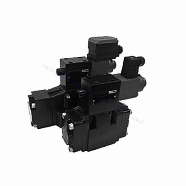
Válvula hidráulica redutora de pressão proporcional de 3 vias operada por piloto da série 3DRE/M(E)
Como um dos fabricantes, fornecedores e exportadores de produtos mecânicos de cilindros hidráulicos, oferecemos cilindros hidráulicos e muitos outros produtos.
Entre em contato conosco para obter detalhes.
Correio eletrônico:sales@hydraulic-cylinders.net
Fabricante, fornecedor e exportador de cilindros hidráulicos.
Válvula hidráulica redutora de pressão proporcional de 3 vias operada por piloto da série 3DRE/M(E)
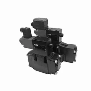
A válvula hidráulica redutora de pressão proporcional de 3 vias com acionamento por piloto da série 3DRE/M(E) é um componente hidráulico de ponta projetado para fornecer controle preciso de pressão em sistemas hidráulicos. Com sua avançada tecnologia de controle proporcional com acionamento por piloto, esta válvula garante regulação precisa, desempenho eficiente e operação confiável.
A válvula hidráulica redutora de pressão proporcional de 3 vias da série 3DRE/M(E) oferece aos sistemas hidráulicos controle preciso de pressão, eficiência e desempenho confiável. Com sua avançada tecnologia de controle proporcional e configuração de 3 vias, esta válvula oferece versatilidade e flexibilidade na regulação de pressão em diferentes circuitos hidráulicos. Seguindo os métodos de uso e as diretrizes de manutenção recomendadas, você pode maximizar os benefícios e a vida útil da válvula da série 3DRE/M(E), otimizando o controle de pressão e o desempenho geral do seu sistema hidráulico. Atualize seu sistema hidráulico hoje mesmo e experimente uma regulação de pressão superior com a válvula hidráulica redutora de pressão proporcional de 3 vias da série 3DRE/M(E).
Válvula hidráulica redutora de pressão proporcional de 3 vias operada por piloto da série 3DRE/M(E) - Principais características:
- Controle de pressão proporcional:
- A válvula da série 3DRE/M(E) oferece controle de pressão preciso e proporcional, permitindo o ajuste dinâmico dos níveis de pressão hidráulica.
- Essa funcionalidade garante uma regulação precisa da pressão, mantendo uma pressão constante e segura dentro do sistema hidráulico.
- Projeto operado por piloto:
- Graças ao seu design operado por piloto, a válvula oferece maior precisão e capacidade de resposta no controle de pressão.
- Utiliza uma válvula piloto para modular a válvula principal, permitindo ajustes precisos e melhor controle sobre a redução de pressão.
- Configuração de 3 vias:
- A válvula da série 3DRE/M(E) apresenta uma configuração versátil de 3 vias, proporcionando flexibilidade no controle da pressão em diferentes circuitos hidráulicos.
- Permite a redução simultânea da pressão em um circuito enquanto se fornece pressão a outro.
- Desempenho eficiente:
- Ao utilizar tecnologia avançada de controle proporcional, a válvula garante um desempenho eficiente, otimizando o consumo de energia e reduzindo os custos operacionais.
- Isso minimiza as flutuações de pressão, aumentando a eficiência do sistema e contribuindo para a produtividade geral.
Parâmetros da válvula hidráulica redutora de pressão proporcional de 3 vias operada por piloto da série 3DRE/M(E):
| Hidráulico | ||||||||
| Posição de instalação | opcional, de preferência horizontal | |||||||
| Tamanho | 6 | 10 | ||||||
| Peso | 4WRA…L2X | Kg | 2 | 6.6 | ||||
| 4WRAE…L2X | 2.2 | 6.8 | ||||||
| Vazão nominal qnom, quando Δp = 10 bar | L/min | 7, 15, 26 | 30, 60 | |||||
| Histerese | % | ≤5 | ||||||
| Repetibilidade | % | ≤1 | ||||||
| Sensibilidade de resposta | % | ≤0,5 | ||||||
| Pressão máxima de operação | Porto s ABP | bar | 315 | |||||
| Porto T | bar | 210 | ||||||
| Fluido | Óleo mineral adequado para vedação NBR e FKM | |||||||
| Éster de fosfato para selo FKM | ||||||||
| Faixa de temperatura do fluido | 4WRA…L2X | °C | -20℃ a 70℃ (-4°F a 158°F) | |||||
| 4WRAE…L2X | °C | -20℃ a 50℃ (-4° F a 122° F) | ||||||
| Faixa de viscosidade | mm²/s | 20 a 380 (de preferência 30 a 46) | ||||||
| Grau de contaminação | NAS1638 classe 9 ou ISO 4406 classe 20/18/15 | |||||||
| Dados elétricos | ||||||||
| 1) solenóide | ||||||||
| Tipo de voltagem | DC | |||||||
| Sinal de valor de comando | ±10V ou 4~20mA | |||||||
| Corrente máxima por solenóide | UM | 2.5 | 1.5 | 0.8 | ||||
| Resistência da bobina | Valor frio | Ω | 2 | 4.8 | 19.5 | |||
| Valor máximo de aquecimento | 3 | 7.2 | 28.8 | |||||
| Obrigação | % | ED100% | ||||||
| Temperatura da bobina | °C | 150 | ||||||
| Proteção de válvulas conforme EN 60529 | IP 65 | |||||||
| 2) Eletrônica de controle | ||||||||
| Amplificador | 4WRA…L2X | VT-VSPA2-L2X | ||||||
| 4WRAE…L2X | Integrado na válvula (OBE) | |||||||
| Tensão de operação | Tensão nominal | VDC | 24 | |||||
| Valor limite inferior | V | 21/22(4WRA), 19(4WRAE) | ||||||
| Valor limite superior | V | 35 | ||||||
| Consumo de corrente do amplificador | Imax | UM | <1,8 | |||||
| Imax | UM | 3 | ||||||
Vantagens da válvula hidráulica redutora de pressão proporcional de 3 vias da série 3DREP(E):
• A válvula de alívio operada por piloto é usada para a redução de pressão de P para A e para a função de transbordamento de A para T.
• Utilizado para montagem na subplaca inferior, acionado por solenóide proporcional.
• A superfície de montagem está em conformidade com as normas DIN24 340, tipo A, ISO4401 e CETOP-RP 121H.
• É possível selecionar a pressão máxima de segurança.
• Alinhamento da mola do carretel
• Controlador eletrônico 3DRE: amplificador com especificação de placa europeia VT-VSPA1-1/VT-VSPD-1
• No ponto de ajuste, a curva característica de pressão é linear.
• Controlador eletrônico integrado da série 3DRE(M)E
• O valor de ajuste foi causado por erro de fabricação – o desvio da curva característica de pressão é pequeno.
• A inclinação do aumento e da diminuição da pressão pode ser ajustada independentemente.
Método de uso da válvula hidráulica redutora de pressão proporcional de 3 vias da série 3DREP(E):
- Avaliação do Sistema:
- Avalie seu sistema hidráulico e identifique os requisitos específicos de controle de pressão para cada circuito.
- Determine se a válvula da série 3DRE/M(E) é adequada com base em sua faixa de pressão, capacidade de fluxo e compatibilidade com seu sistema.
- Seleção de válvulas:
- Selecione a variante apropriada da válvula da série 3DRE/M(E) com base nos parâmetros do seu sistema, faixa de pressão e requisitos de fluxo.
- Considere a classificação de pressão máxima, o tempo de resposta e as condições operacionais.
- Instalação:
- Siga cuidadosamente as instruções de instalação do fabricante, garantindo o alinhamento adequado e a montagem segura da válvula.
- Conecte a válvula ao sistema hidráulico, garantindo conexões sem vazamentos e alinhamento adequado da direção do fluxo.
- Ajuste de pressão:
- Utilize o mecanismo de controle da válvula piloto fornecido com a válvula da série 3DRE/M(E) para ajustar o nível de redução de pressão desejado para cada circuito.
- Ajuste gradualmente o controle da válvula piloto para atingir o controle de pressão desejado, monitorando as leituras do manômetro e a resposta do sistema.
Como ajustar válvulas hidráulicas?
Ajustar válvulas hidráulicas é uma tarefa crucial para garantir o controle adequado do fluxo e o desempenho do sistema em aplicações hidráulicas. Aqui está um guia passo a passo sobre como ajustar válvulas hidráulicas:
- Identifique a válvula:
- Determine o tipo de válvula hidráulica que você precisa ajustar: válvula de alívio de pressão, válvula de controle de fluxo, válvula direcional ou qualquer outro tipo.
- Localize a válvula em seu sistema hidráulico. Ela pode estar localizada perto da bomba, no coletor de válvulas de controle ou dentro de componentes hidráulicos específicos.
- Reúna as ferramentas necessárias:
- Antes de iniciar o processo de ajuste, reúna as ferramentas necessárias, como uma chave ajustável, uma chave de fenda, um manômetro (se aplicável) e quaisquer ferramentas especializadas recomendadas pelo fabricante da válvula.
- Entenda a função da válvula:
- Familiarize-se com a finalidade e a função da válvula que você está ajustando. Consulte a documentação técnica da válvula ou as diretrizes do fabricante para obter detalhes específicos.
- Determine a configuração desejada:
- Identifique a configuração ou o parâmetro desejado que você quer alcançar ajustando a válvula. Isso pode ser pressão, vazão, direção ou qualquer outro parâmetro ajustável, dependendo do tipo de válvula.
- Verificações preliminares:
- Certifique-se de que o sistema hidráulico esteja despressurizado antes de tentar qualquer ajuste. Isso pode ser feito desligando o sistema e aliviando a pressão residual através das válvulas apropriadas.
- Aceda ao Mecanismo de Ajuste:
- Localize o mecanismo de ajuste na válvula. Pode ser um parafuso de fixação, uma porca de travamento, um botão ou outros dispositivos semelhantes, dependendo do tipo de válvula.
- Algumas válvulas podem exigir a remoção de uma tampa ou cobertura protetora para acessar o mecanismo de ajuste.
- Faça ajustes incrementais:
- Utilizando a ferramenta apropriada, faça pequenos ajustes incrementais na válvula de acordo com a configuração desejada.
- Siga as instruções do fabricante para determinar a direção (sentido horário ou anti-horário) e o grau de ajuste necessário.
- Faça ajustes graduais e verifique periodicamente a resposta do sistema para garantir que você esteja caminhando na direção desejada.
- Testar e monitorar:
- Após cada ajuste, ative o sistema hidráulico e observe seu desempenho.
- Utilize ferramentas de medição apropriadas (manômetro, medidor de vazão, etc.) para verificar se a válvula está operando dentro da faixa desejada.
- Monitore o sistema para detectar quaisquer anormalidades ou comportamentos inesperados. Se necessário, faça ajustes adicionais para otimizar a configuração da válvula.
- Bloquear o ajuste (se aplicável):
- Após atingir a configuração desejada, fixe o mecanismo de ajuste para evitar alterações indesejadas.
- Isso pode ser feito apertando uma porca de fixação, prendendo um parafuso de ajuste ou usando qualquer outro método recomendado pelo fabricante da válvula.
Aptidão e capacidade da fábrica:
(1) Montagem
Temos uma plataforma de montagem de pesquisa e desenvolvimento independente de primeira classe. A oficina de produção de cilindros hidráulicos tem quatro linhas de montagem semiautomáticas de cilindros de elevação e uma linha de montagem automática de cilindros de inclinação, com uma capacidade de produção anual projetada de 1 milhão de peças. A oficina de cilindros especiais é equipada com várias especificações de um sistema de montagem de limpeza semiautomática com uma capacidade de produção anual projetada de 200.000 peças e equipada com famosos equipamentos de usinagem CNC, um centro de usinagem, um equipamento especial de processamento de cilindros de alta precisão, uma máquina de solda robotizada, uma máquina de limpeza automática, uma máquina de montagem automática de cilindros e uma linha de produção de pintura automática. O equipamento crítico existente é de mais de 300 conjuntos (conjuntos). A alocação ideal e o uso eficiente dos recursos do equipamento garantem os requisitos de precisão dos produtos e atendem às necessidades de alta qualidade dos produtos.


(2) Usinagem
A oficina de usinagem é equipada com um centro de torneamento de trilho inclinado personalizado, um centro de usinagem, uma máquina de brunimento de alta velocidade, um robô de soldagem e outros equipamentos relacionados, que podem lidar com o processamento de tubos de cilindros com diâmetro interno máximo de 400 mm e comprimento máximo de 6 metros.

(3) Soldagem

(4) Pintura e revestimento
Com linhas de revestimento de tinta à base de água automáticas de cilindros de pequeno e médio porte, para obter carregamento e descarregamento automáticos de robôs e pulverização automática, a capacidade projetada é de 4.000 peças por turno;
Também temos uma linha de produção de tinta semiautomática para cilindros grandes, acionada por uma corrente elétrica, com capacidade de projeto de 60 caixas por turno.


(5) Testes
Temos instalações de inspeção e bancos de teste de primeira classe para garantir que o desempenho do cilindro atenda aos requisitos.

Somos um dos melhores fabricantes de cilindros hidráulicos. Oferecemos cilindros hidráulicos completos. Também fornecemos os correspondentes caixas de câmbio agrícolas. Exportamos nossos produtos para clientes em todo o mundo e conquistamos uma boa reputação devido à qualidade superior de nossos produtos e ao serviço pós-venda. Convidamos clientes nacionais e estrangeiros a entrar em contato conosco para negociar negócios, trocar informações e cooperar conosco!
Cilindro hidráulico Aplicação:
