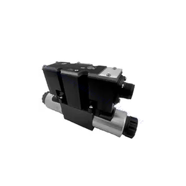
Válvula hidráulica redutora de pressão proporcional de 3 vias série 3DREP(E)
Como um dos fabricantes, fornecedores e exportadores de produtos mecânicos de cilindros hidráulicos, oferecemos cilindros hidráulicos e muitos outros produtos.
Entre em contato conosco para obter detalhes.
Correio eletrônico:sales@hydraulic-cylinders.net
Fabricante, fornecedor e exportador de cilindros hidráulicos.
Válvula hidráulica redutora de pressão proporcional de 3 vias série 3DREP(E)
A válvula hidráulica redutora de pressão proporcional de 3 vias da série 3DREP(E) é um componente hidráulico de última geração, projetado especificamente para fornecer controle preciso da pressão em sistemas hidráulicos. Com sua avançada tecnologia de controle proporcional, esta válvula garante regulagem precisa, eficiência e desempenho confiável.
A válvula hidráulica redutora de pressão proporcional de 3 vias da série 3DREP(E) proporciona aos sistemas hidráulicos controle preciso da pressão, eficiência e desempenho confiável. Com sua avançada tecnologia de controle proporcional e configuração de 3 vias, esta válvula oferece versatilidade e flexibilidade na regulação da pressão em diferentes circuitos hidráulicos. Seguindo os métodos de uso e as diretrizes de manutenção recomendados, você pode maximizar os benefícios e a longevidade da válvula da série 3DREP(E), otimizando o controle da pressão e o desempenho geral do seu sistema hidráulico. Atualize sua configuração hidráulica hoje mesmo e experimente uma regulação de pressão superior com a válvula hidráulica redutora de pressão proporcional de 3 vias da série 3DREP(E).
Principais características da válvula hidráulica redutora de pressão proporcional de 3 vias da série 3DREP(E):
- Controle de pressão proporcional:
- A válvula da série 3DREP(E) oferece controle de pressão preciso e proporcional, permitindo o ajuste dinâmico dos níveis de pressão hidráulica.
- Ele garante uma regulagem precisa da pressão, mantendo uma pressão consistente e segura dentro do sistema hidráulico.
- Configuração de 3 vias:
- Esta válvula apresenta uma configuração de 3 vias, proporcionando versatilidade e flexibilidade no controle de pressão em diferentes circuitos hidráulicos.
- Ele permite a redução simultânea da pressão em um circuito enquanto fornece pressão para outro circuito.
- Eficiência aprimorada do sistema:
- Com sua tecnologia de controle proporcional, a válvula da série 3DREP(E) permitiu um ajuste preciso da pressão, resultando em maior eficiência do sistema e menor consumo de energia.
- Ao manter níveis de pressão ideais, ele minimiza as flutuações de pressão, otimiza o desempenho do sistema e reduz os custos operacionais.
- Desempenho confiável:
- A válvula da série 3DREP(E) foi projetada para oferecer desempenho consistente e confiável sob condições operacionais variadas.
- Ele garante controle de pressão estável, reduzindo o risco de falhas no sistema, danos aos componentes e possível tempo de inatividade.
Válvula hidráulica redutora de pressão proporcional de 3 vias série 3DREP(E) Parâmetro:
| Hidráulico | ||||
| Especificações | 3DREP6…L2X | 3DREPE6…L2X | ||
| Posição de instalação | Opcional, de preferência horizontal | |||
| Peso | KG | 2 | 2.2 | |
| Faixa de temperatura ambiente | °C | -20 a +70 | -20 a +50 | |
| Taxa de fluxo máxima | L/min | 15 (Δp = 50 bar) | ||
| Histerese | % | ≤5 | ||
| Repetibilidade | % | ≤1 | ||
| Sensibilidade de resposta | % | ≤0,5 | ||
| Pressão máxima de operação | Porto P | bar | 20 a 100, estágio de pressão 16 | |
| 30 a 100, estágio de pressão 25 | ||||
| 50 a 100, estágio de pressão 45 | ||||
| Porto T | 0 a 3 | |||
| Fluido | Óleo mineral adequado para vedação NBR e FKM | |||
| Éster de fosfato para selo FKM | ||||
| Faixa de temperatura do fluido | °C | -20 a +80 | ||
| Faixa de viscosidade | milímetros2/s | 20 a 380 (de preferência 30 a 46) | ||
| Grau de contaminação | Grau máximo permitido de contaminação do fluido: Classe 9 e ISO4406 Classe 20/18/15 | |||
| Dados elétricos | ||||
| solenóide | ||||
| Especificações | 3DREP6…L2X | 3DREPE6…L2X | ||
| Dados elétricos | DC | |||
| Sinal de valor de comando | – | ±10V | ||
| Corrente máxima por solenóide | UM | 1.5 | 2.5 | |
| Resistência da bobina | Valor frio a 20 ℃ | Ω | 4.8 | 2 |
| Valor máximo de aquecimento | 7.2 | 3 | ||
| Obrigação | % | ED100% | ||
| Temperatura da bobina | °C | para 150 | ||
| Proteção de válvulas conforme EN 60529 | IP 65 | |||
| Amplificador | VT-VSPA2-50-L1X | integrado | ||
| Tensão de operação | Tensão nominal | VDC | 24 | |
| Valor limite inferior | V | 19 | ||
| Valor limite superior | V | 35 | ||
| Consumo de corrente do amplificador | Imax | UM | 1.8 | |
| Imax | UM | 4 | ||
Vantagens da válvula hidráulica redutora de pressão proporcional de 3 vias da série 3DREP(E):
• Válvula proporcional de ação direta, usada para controlar a pressão e a direção do fluxo
• Instalação tipo painel
• O núcleo da válvula é acionado pelo solenóide proporcional através da conexão roscada, e a bobina pode ser removida separadamente
• Alinhamento da mola do carretel
• Opcional com amplificador integrado, interface de entrada tipo 3DREPE6…L2X A1 ou F1
• Suporte de fornecimento de amplificador externo
Método de uso da válvula hidráulica redutora de pressão proporcional de 3 vias da série 3DREP(E):
- Avaliação do Sistema:
- Avalie seu sistema hidráulico e identifique os requisitos específicos de controle de pressão para cada circuito.
- Determine se a válvula da série 3DREP(E) é adequada com base em sua faixa de pressão, capacidade de fluxo e compatibilidade com seu sistema.
- Seleção de válvulas:
- Escolha a variante apropriada da válvula da série 3DREP(E) com base nos parâmetros do seu sistema, faixa de pressão e requisitos de fluxo.
- Considere a classificação de pressão máxima, o tempo de resposta e as condições operacionais.
- Instalação:
- Siga cuidadosamente as instruções de instalação do fabricante, garantindo o alinhamento adequado e a montagem segura da válvula.
- Conecte a válvula ao sistema hidráulico, garantindo conexões sem vazamentos e alinhamento adequado da direção do fluxo.
- Ajuste de pressão:
- Utilize o sinal de controle proporcional ou o mecanismo de ajuste fornecido com a válvula da série 3DREP(E) para definir o nível de redução de pressão desejado para cada circuito.
- Ajuste a válvula incrementalmente, monitorando as leituras do manômetro e a resposta do sistema para obter um controle preciso da pressão.
Como ajustar a válvula de alívio hidráulica?
Ajustar uma válvula de alívio hidráulica é uma tarefa importante para garantir a regulação adequada da pressão e o desempenho do sistema em aplicações hidráulicas. Aqui está um guia passo a passo sobre como ajustar uma válvula de alívio hidráulica:
- Identifique a válvula de alívio:
- Localize a válvula de alívio no seu sistema hidráulico. Ela normalmente está posicionada perto da bomba ou na linha de pressão.
- Reúna as ferramentas necessárias:
- Antes de iniciar o processo de ajuste, reúna as ferramentas necessárias, como um manômetro, uma chave ajustável e uma chave de fenda.
- Medir a pressão atual:
- Conecte o manômetro a uma porta de teste ou à saída da válvula de alívio. Certifique-se de que o manômetro seja compatível com a pressão operacional do sistema.
- Ative o sistema hidráulico e observe a leitura de pressão no manômetro. Isso fornecerá uma base para o processo de ajuste.
- Determine a pressão desejada:
- Consulte as especificações do sistema ou as diretrizes do fabricante para determinar a pressão desejada para o seu sistema hidráulico.
- Certifique-se de que a faixa de pressão da válvula de alívio seja adequada à configuração de pressão desejada.
- Prepare-se para o ajuste:
- Identifique o mecanismo de ajuste da válvula de alívio. Pode ser um parafuso de fixação, uma porca de fixação ou uma ferramenta similar.
- Use uma chave ajustável ou uma ferramenta apropriada para afrouxar a porca de fixação, se houver, sem mexer no parafuso de ajuste.
- Ajuste a válvula de alívio:
- Girar o parafuso de ajuste no sentido horário aumentará a configuração de pressão, enquanto girá-lo no sentido anti-horário diminuirá a configuração de pressão.
- Faça pequenos ajustes de cada vez, normalmente um quarto ou meia volta, para evitar mudanças bruscas de pressão.
- Monitore o manômetro enquanto faz ajustes e certifique-se de que a pressão permaneça dentro da faixa desejada.
- Bloqueie o ajuste:
- Depois de atingir a pressão desejada, aperte a porca de fixação (se houver) para fixar o parafuso de ajuste no lugar.
- Certifique-se de que o parafuso de ajuste esteja firmemente apertado, mas evite apertar demais, pois isso pode afetar o desempenho da válvula.
- Teste e verifique:
- Ative o sistema hidráulico e observe o manômetro para garantir que a válvula de alívio mantenha a pressão desejada em condições normais de operação.
- Monitore o sistema em busca de anormalidades ou flutuações de pressão. Se necessário, faça ajustes adicionais para refinar a configuração da válvula de alívio.
Aptidão e capacidade da fábrica:
(1) Montagem
Temos uma plataforma de montagem de pesquisa e desenvolvimento independente de primeira classe. A oficina de produção de cilindros hidráulicos tem quatro linhas de montagem semiautomáticas de cilindros de elevação e uma linha de montagem automática de cilindros de inclinação, com uma capacidade de produção anual projetada de 1 milhão de peças. A oficina de cilindros especiais é equipada com várias especificações de um sistema de montagem de limpeza semiautomática com uma capacidade de produção anual projetada de 200.000 peças e equipada com famosos equipamentos de usinagem CNC, um centro de usinagem, um equipamento especial de processamento de cilindros de alta precisão, uma máquina de solda robotizada, uma máquina de limpeza automática, uma máquina de montagem automática de cilindros e uma linha de produção de pintura automática. O equipamento crítico existente é de mais de 300 conjuntos (conjuntos). A alocação ideal e o uso eficiente dos recursos do equipamento garantem os requisitos de precisão dos produtos e atendem às necessidades de alta qualidade dos produtos.


(2) Usinagem
A oficina de usinagem é equipada com um centro de torneamento de trilho inclinado personalizado, um centro de usinagem, uma máquina de brunimento de alta velocidade, um robô de soldagem e outros equipamentos relacionados, que podem lidar com o processamento de tubos de cilindros com diâmetro interno máximo de 400 mm e comprimento máximo de 6 metros.

(3) Soldagem

(4) Pintura e revestimento
Com linhas de revestimento de tinta à base de água automáticas de cilindros de pequeno e médio porte, para obter carregamento e descarregamento automáticos de robôs e pulverização automática, a capacidade projetada é de 4.000 peças por turno;
Também temos uma linha de produção de tinta semiautomática para cilindros grandes, acionada por uma corrente elétrica, com capacidade de projeto de 60 caixas por turno.


(5) Testes
Temos instalações de inspeção e bancos de teste de primeira classe para garantir que o desempenho do cilindro atenda aos requisitos.

Somos um dos melhores fabricantes de cilindros hidráulicos. Oferecemos cilindros hidráulicos completos. Também fornecemos os correspondentes caixas de câmbio agrícolas. Exportamos nossos produtos para clientes em todo o mundo e conquistamos uma boa reputação devido à qualidade superior de nossos produtos e ao serviço pós-venda. Convidamos clientes nacionais e estrangeiros a entrar em contato conosco para negociar negócios, trocar informações e cooperar conosco!
Cilindro hidráulico Aplicação:
