


4WRA(E) Series Direct operated Proportional Directional Hydraulic Valve
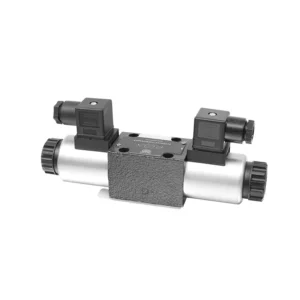

The 4WRA(E) series direct operated proportional directional hydraulic valve is a state-of-the-art hydraulic component designed to provide precise control and efficient operation in hydraulic systems. With its direct-operated proportional directional control technology, this valve offers accurate flow control, seamless direction changes, and optimized performance.
The 4WRA(E) series direct operated proportional directional hydraulic valve empowers hydraulic systems with precise flow control, versatile directional changes, and optimal energy efficiency. Its direct-operated proportional control technology ensures accurate and responsive operation, while the high flow capacity and energy-efficient design contribute to enhanced system performance. By following the recommended usage methods and maintenance guidelines, you can maximize the benefits and longevity of the 4WRA(E) series valve, elevating your hydraulic system to new levels of precision and efficiency. Upgrade your hydraulic setup today and experience the power of the 4WRA(E) series direct operated proportional directional hydraulic valve.
4WRA(E) Series Direct operated Proportional Directional Hydraulic Valve Key Characteristics:
- Direct Operated Proportional Control:
- The 4WRA(E) series valve utilizes direct-operated proportional control, allowing for precise and immediate response to control signals.
- This feature ensures accurate flow control and seamless transitions between different hydraulic functions.
- High Flow Capacity:
- With its robust design, the valve offers high flow capacity, making it suitable for applications requiring substantial hydraulic power.
- It allows for efficient handling of large fluid volumes, contributing to enhanced system performance.
- Versatile Directional Control:
- The 4WRA(E) series valve provides versatile directional control, enabling smooth and precise changes in hydraulic fluid direction.
- It allows for the seamless activation of hydraulic components such as cylinders, motors, and actuators in different directions.
- Energy Efficiency:
- Designed with energy efficiency in mind, this valve minimizes pressure drops and optimizes flow control, resulting in reduced energy consumption.
- By efficiently managing hydraulic power, it helps maximize system performance while minimizing operational costs.
4WRA(E) Series Direct operated Proportional Directional Hydraulic Valve Parameter:
| Hydraulic | ||||||||
| Installation position | optional, preferably horizontal | |||||||
| Size | 6 | 10 | ||||||
| Weight | 4WRA…L2X | Kg | 2 | 6.6 | ||||
| 4WRAE…L2X | 2.2 | 6.8 | ||||||
| Rated flow qnom,when Δp = 10 bar | L/min | 7、15、26 | 30、60 | |||||
| Hysteresis | % | ≤5 | ||||||
| Repeatability | % | ≤1 | ||||||
| Response sensitivity | % | ≤0.5 | ||||||
| Max. operating pressure | Port s A B P | bar | 315 | |||||
| Port T | bar | 210 | ||||||
| Fluid | Mineral oil suitable for NBR and FKM seal | |||||||
| Phosphate ester for FKM seal | ||||||||
| Fluid temperature range | 4WRA…L2X | ℃ | -20℃ to 70℃(-4°F to 158°F) | |||||
| 4WRAE…L2X | ℃ | -20℃ to 50℃(-4° F to 122° F) | ||||||
| Viscosity range | mm²/s | 20 to 380(preferably 30 to 46) | ||||||
| Degree of contamination | NAS1638 class9 or ISO 4406 class 20/18/15 | |||||||
| Electrical data | ||||||||
| 1)solenoid | ||||||||
| Voltage type | DC | |||||||
| Command value signal | ±10V or 4~20mA | |||||||
| Max. current per solenoid | A | 2.5 | 1.5 | 0.8 | ||||
| Coil resistance | Cold value | Ω | 2 | 4.8 | 19.5 | |||
| Max. warm value | 3 | 7.2 | 28.8 | |||||
| Duty | % | ED100% | ||||||
| Coil temperature | ℃ | 150 | ||||||
| Valve protection to EN 60529 | IP 65 | |||||||
| 2)Control electronics | ||||||||
| Ampilfier | 4WRA…L2X | VT-VSPA2-L2X | ||||||
| 4WRAE…L2X | Integrated in the valve(OBE) | |||||||
| Operating voltage | Nominal voltage | VDC | 24 | |||||
| Lower limiting value | V | 21/22(4WRA),19(4WRAE) | ||||||
| Upper limiting value | V | 35 | ||||||
| Amplifier current consumption | Imax | A | <1.8 | |||||
| Imax | A | 3 | ||||||
4WRA(E) Series Direct operated Proportional Directional Hydraulic Valve Advantages:
• Direct-acting proportional directional valve, used to control the flow and direction of liquid flow
• Panel type installation
• The proportional solenoid actuates the valve core through the threaded connection, and the coil can be removed separately
• Spool spring alignment alignment
• Optional with built-in amplifier, 4WRAE…L2X type input can be A1 or F1
• Supporting supply of external amplifier
Usage Method Of 4WRA(E) Series Direct operated Proportional Directional Hydraulic Valve:
- System Evaluation:
- Evaluate your hydraulic system and identify the specific flow control and directional requirements.
- Determine if the 4WRA(E) series valve is suitable based on its flow capacity, pressure rating, and compatibility with your system.
- Valve Selection:
- Select the appropriate variant of the 4WRA(E) series valve based on your system parameters, flow requirements, and directional control needs.
- Consider factors such as maximum flow rate, pressure rating, response time, and operational conditions.
- Installation:
- Follow the manufacturer’s installation instructions carefully, ensuring proper alignment and secure valve mounting.
- Connect the valve to the hydraulic system, ensuring leak-free connections and proper flow direction alignment.
- Control Signal Connection:
- Connect the control signal wires of the valve to the appropriate control device, such as a proportional amplifier or electronic control unit.
- Ensure proper wiring and compatibility between the valve and the control device to enable accurate and responsive control.
How To Adjust Valve Lash On Hydraulic Lifters?
Adjusting valve lash on hydraulic lifters is a crucial maintenance task to ensure proper engine performance and prevent issues such as noisy valves or reduced power. Here’s a step-by-step guide on how to adjust valve lash on hydraulic lifters:
- Preparation:
- Ensure the engine is off and cool before starting the adjustment process.
- Familiarize yourself with the engine’s firing order and the specific valve lash specifications provided by the manufacturer for your engine model.
- Identify the Correct Cylinder:
- Locate the firing position of the engine by referring to the engine’s firing order diagram.
- Identify the cylinder that corresponds to the specific valve you want to adjust.
- Position the Cylinder:
- Rotate the engine crankshaft manually using a socket wrench or the engine’s built-in turning mechanism.
- Position the cylinder you want to adjust at the top dead center (TDC) on the compression stroke. You can do this by aligning the timing marks on the crankshaft pulley or using a piston stop tool.
- Loosen the Rocker Arm:
- Locate the rocker arm on the specific valve you want to adjust.
- Loosen the rocker arm nut or adjuster screw using an appropriate wrench or socket.
- Adjust the Valve Lash:
- With the rocker arm loose, you can now adjust the valve lash. The valve lash is the clearance between the rocker arm and the valve stem.
- Use a feeler gauge to measure the existing valve lash. Insert the appropriate thickness gauge between the rocker arm and the valve stem.
- If the clearance is too tight, meaning the feeler gauge does not fit or has excessive resistance, you need to increase the valve lash. If the clearance is too loose, meaning the feeler gauge slides in too easily, you need to decrease the valve lash.
- To adjust the valve lash, tighten or loosen the rocker arm nut or adjuster screw accordingly. Refer to the manufacturer’s specifications for the recommended amount of adjustment to be made.
- Recheck the Valve Lash:
- After making the adjustment, recheck the valve lash using the feeler gauge to ensure it falls within the recommended specifications.
- Repeat the adjustment process if necessary until the correct valve lash is achieved.
- Repeat for Other Cylinders:
- Proceed to the next cylinder in the firing order and repeat steps 4 to 6 for each cylinder you want to adjust.
- Remember to rotate the crankshaft and position each cylinder at TDC on the compression stroke before adjusting its valve lash.
- Secure the Rocker Arm:
- Once the valve lash is properly adjusted for each cylinder, tighten the rocker arm nut or adjuster screw to the manufacturer’s recommended torque specification.
- Double-check that the valve lash remains within the specified range after tightening.
- Final Checks:
- Rotate the engine crankshaft a few times to ensure smooth rotation and check for any unusual noises or resistance.
- Start the engine and listen for any abnormal valve noises. If you hear excessive tapping or knocking, recheck the valve lash adjustment.
Aptidão e capacidade da fábrica:
(1) Montagem
Temos uma plataforma de montagem de pesquisa e desenvolvimento independente de primeira classe. A oficina de produção de cilindros hidráulicos tem quatro linhas de montagem semiautomáticas de cilindros de elevação e uma linha de montagem automática de cilindros de inclinação, com uma capacidade de produção anual projetada de 1 milhão de peças. A oficina de cilindros especiais é equipada com várias especificações de um sistema de montagem de limpeza semiautomática com uma capacidade de produção anual projetada de 200.000 peças e equipada com famosos equipamentos de usinagem CNC, um centro de usinagem, um equipamento especial de processamento de cilindros de alta precisão, uma máquina de solda robotizada, uma máquina de limpeza automática, uma máquina de montagem automática de cilindros e uma linha de produção de pintura automática. O equipamento crítico existente é de mais de 300 conjuntos (conjuntos). A alocação ideal e o uso eficiente dos recursos do equipamento garantem os requisitos de precisão dos produtos e atendem às necessidades de alta qualidade dos produtos.


(2) Usinagem
A oficina de usinagem é equipada com um centro de torneamento de trilho inclinado personalizado, um centro de usinagem, uma máquina de brunimento de alta velocidade, um robô de soldagem e outros equipamentos relacionados, que podem lidar com o processamento de tubos de cilindros com diâmetro interno máximo de 400 mm e comprimento máximo de 6 metros.


(3) Soldagem


(4) Pintura e revestimento
Com linhas de revestimento de tinta à base de água automáticas de cilindros de pequeno e médio porte, para obter carregamento e descarregamento automáticos de robôs e pulverização automática, a capacidade projetada é de 4.000 peças por turno;
Também temos uma linha de produção de tinta semiautomática para cilindros grandes, acionada por uma corrente elétrica, com capacidade de projeto de 60 caixas por turno.


(5) Testes
Temos instalações de inspeção e bancos de teste de primeira classe para garantir que o desempenho do cilindro atenda aos requisitos.


We are one of the best hydraulic cylinder manufacturers. We can offer comprehensive hydraulic cylinders. We also provide corresponding caixas de câmbio agrícolas. Exportamos nossos produtos para clientes em todo o mundo e conquistamos uma boa reputação devido à qualidade superior de nossos produtos e ao serviço pós-venda. Convidamos clientes nacionais e estrangeiros a entrar em contato conosco para negociar negócios, trocar informações e cooperar conosco!