
4WRKE Series Pilot Operated Proportional Directional Hydraulic Valve
Como um dos fabricantes, fornecedores e exportadores de produtos mecânicos de cilindros hidráulicos, oferecemos cilindros hidráulicos e muitos outros produtos.
Entre em contato conosco para obter detalhes.
Correio eletrônico:sales@hydraulic-cylinders.net
Fabricante, fornecedor e exportador de cilindros hidráulicos.
4WRKE Series Pilot Operated Proportional Directional Hydraulic Valve
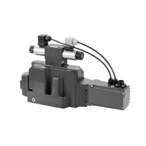
The 4WRKE series pilot-operated proportional directional hydraulic valve is a cutting-edge hydraulic component designed to provide superior precision, control, and efficiency in hydraulic systems. With its advanced pilot-operated proportional control technology, this valve enables accurate flow regulation and seamless directional changes.
The 4WRKE series pilot-operated proportional directional hydraulic valve empowers hydraulic systems with precise flow control, versatile directional changes, and energy efficiency. Its pilot-operated proportional control technology ensures accurate and responsive flow adjustment, while the high flow capacity guarantees reliable performance even in demanding applications. By following the recommended usage methods and maintenance guidelines, you can maximize the benefits and longevity of the 4WRKE series valve, elevating your hydraulic system to new levels of precision and control. Upgrade your hydraulic setup today and experience the power of the 4wrke series pilot-operated proportional directional hydraulic valve.
4WRKE Series Pilot Operated Proportional Directional Hydraulic Valve Key Characteristics:
- Pilot-Operated Proportional Control
- The 4WRKE series valve utilizes pilot-operated proportional control technology, allowing precise and proportional flow adjustment based on control signals.
- This feature ensures accurate and responsive control, resulting in improved system performance, reduced energy consumption, and enhanced productivity.
- Versatile Directional Control
- This valve offers versatile control over hydraulic fluid direction, making it suitable for a wide range of applications.
- It enables seamless activation and deactivation of hydraulic components such as cylinders, motors, and actuators in different directions, enhancing system flexibility and adaptability.
- High Flow Capacity
- The 4WRKE series valve is engineered to handle high flow rates, making it ideal for applications that require substantial hydraulic power.
- Its robust construction ensures reliable performance even under demanding conditions, providing consistent and efficient flow control.
- Energy Efficiency
- By incorporating pilot-operated proportional control, this valve minimizes pressure drops and optimizes energy usage.
- It helps reduce energy consumption, resulting in cost savings and environmental benefits.
4WRKE Series Pilot Operated Proportional Directional Hydraulic Valve Parameter:
| General | |||||||||
| Size | 10 | 16 | 25 | 27 | 32 | 35 | |||
| Installation and commissioning guidelines | optional, preferably horizontal | ||||||||
| Storage temperature range | ℃ | – 20 to + 80 | |||||||
| Ambient temperature range | ℃ | -20 to + 50 | |||||||
| Weight | kg | 8.7 | 11.2 | 16.8 | 20 | 37.2 | 72 | ||
| Hydraulic ( measured at p=100bar,with HLP46 at ϑoil =40℃ ±5℃) | |||||||||
| Operating pressure | -Pilot control valve | Pilot oil supply | bar | 25 to 315 | |||||
| -Main valve | Port P A B | bar | Up to 315 | Up to 350 | Up to 350 | Up to 210 | Up to 350 | Up to 350 | |
| Return pressure | Port T
(Pilot oil drain) |
Internal | bar | Static < 10 | |||||
| External | bar | Up to 315 | Up to 250 | Up to 250 | Up to 210 | Up to 250 | Up to 250 | ||
| Port Y | bar | Static < 10 | |||||||
| Nominal flow qVnom ±10% at Δp=10bar (Δp = valve pressure differential) |
L/min | 25 50 | – 125 | – 220 | – – | – 440 | – | ||
| 100 | 180 | 350 | 500 | 600 | 1000 | ||||
| Flow of main valve (max. permissible) | L/min | 170 | 460 | 870 | 1000 | 1600 | 3000 | ||
| Pilot oil flow at port X or Y with a step form of input signal from 0 to 100 % (315 bar) | L/min | 4.1 | 8.5 | 11.7 | 11.7 | 13 | 13 | ||
| Pressure fluid | Mineral oil(HL,HLP)to DIN 51 524 Phosphate ester (HFD-R) | ||||||||
| Fluid temperature range | ℃ | 10 to 80, preferably 40 to 50 | |||||||
| Viscosity range | mm2/s | 20 to 380, preferably 30 to 45 | |||||||
| Degree of contamination | Maximum permissible degree of contamination: NAS 1638. | A filter with a minimum retention rate of βx = 75 is recommended | |||||||
| Pilot control valve | Class 7 | x = 5 | |||||||
| Main valve | Class 9 | x = 7 | |||||||
| Hysteresis | % | ≤1 | |||||||
| Response sensitivity | % | ≤0.5 | |||||||
| Electrical | |||||||||
| Voltage type | DC | ||||||||
| Electrical connection | Plug-in connector to DIN EN175 201-804 | ||||||||
| Power, max. | W | 72 (average = 24W) | |||||||
| Control electronics | Integrated into the valve | ||||||||
4WRKE Series Pilot Operated Proportional Directional Hydraulic Valve Advantages:
• Pilot-operated two-stage proportional directional valve with electrical position feedback of the main spool, used to control the size and direction of the liquid flow
• Sub-plate mounting type connection structure, connection size conforms to ISO 4401 standard
• Spring centred main spool
• With integrated proportional amplifier
• The pilot control is a single-stage proportional directional valve
• The pilot valve is a threaded proportional solenoid, and the coil can be disassembled separately
Usage Method Of 4WRKE Series Pilot Operated Proportional Directional Hydraulic Valve:
- System Evaluation
- Evaluate your hydraulic system and identify the specific flow and directional control requirements.
- Determine if the 4WRKE Series Valve is suitable based on its flow capacity, pressure rating, and compatibility with your system.
- Valve Selection
- Select the appropriate variant of the 4WRKE Series Valve based on your system parameters, flow requirements, and directional control needs.
- Consider factors such as maximum flow rate, pressure rating, response time, and operational conditions.
- Installation
- Follow the manufacturer’s installation instructions carefully, ensuring proper alignment and secure mounting of the valve.
- Make leak-free connections and ensure the correct flow direction alignment to guarantee optimal performance.
- Control Signal Connection
- Connect the control signal wires of the valve to a suitable control device, such as a proportional amplifier or electronic control unit.
- Ensure proper wiring and compatibility between the valve and the control device for accurate and responsive control.
How To Clean Hydraulic Valve Lifters?
Cleaning hydraulic valve lifters is an important maintenance task that helps ensure proper engine performance and reduce noise caused by dirt or debris buildup. Here’s a step-by-step guide on how to clean hydraulic valve lifters:
- Gather the Necessary Tools and Materials:
- New engine oil
- Clean rags or towels
- Engine degreaser or parts cleaner
- Small brush or toothbrush
- Plastic container or tray
- Preparation:
- Allow the engine to cool down completely before starting the cleaning process.
- Remove the valve cover or covers to access the hydraulic valve lifters. Refer to the manufacturer’s instructions or a repair manual for your specific engine to locate and remove the valve cover(s) properly.
- Removal of Hydraulic Valve Lifters:
- Identify the hydraulic valve lifters in the engine.
- One at a time, carefully remove the hydraulic valve lifters from their respective locations. Depending on your engine, you may need to remove other components or parts to access the lifters.
- Place each lifter in a plastic container or tray in the order they were removed. This will help ensure they are reinstalled correctly later.
- Cleaning the Lifters:
- Pour a small amount of engine degreaser or parts cleaner into a container.
- Place one hydraulic valve lifter into the container, ensuring it is fully submerged in the cleaner.
- Allow the lifter to soak for the recommended duration specified by the cleaner manufacturer. This usually ranges from 15 minutes to an hour.
- Use a small brush or toothbrush to gently scrub the lifter’s exterior surfaces, removing any deposits or dirt.
- Rinse the lifter thoroughly with clean water to remove any remaining cleaner or debris.
- Dry the lifter using a clean rag or towel. Ensure there are no traces of moisture before reinstallation.
- Reinstallation:
- Apply a small amount of fresh engine oil to the cleaned lifter’s exterior surface.
- Carefully place the lifter back into its original position in the engine, ensuring it is properly aligned and seated.
- Repeat the cleaning process for each hydraulic valve lifter, following the same steps.
- Once all the lifters are cleaned and reinstalled, make sure they are secured properly.
- Remontagem:
- Reinstall the valve cover(s) according to the manufacturer’s instructions.
- Double-check that all components and parts are properly secured and tightened.
- Test and Inspection:
- Start the engine and let it run for a few minutes to ensure proper operation and to allow the lifters to refill with oil.
- Listen for any abnormal noises or ticking sounds that could indicate further issues.
- If noise or performance problems persist, it may be necessary to consult a professional mechanic for further diagnosis and repair.
Aptidão e capacidade da fábrica:
(1) Montagem
Temos uma plataforma de montagem de pesquisa e desenvolvimento independente de primeira classe. A oficina de produção de cilindros hidráulicos tem quatro linhas de montagem semiautomáticas de cilindros de elevação e uma linha de montagem automática de cilindros de inclinação, com uma capacidade de produção anual projetada de 1 milhão de peças. A oficina de cilindros especiais é equipada com várias especificações de um sistema de montagem de limpeza semiautomática com uma capacidade de produção anual projetada de 200.000 peças e equipada com famosos equipamentos de usinagem CNC, um centro de usinagem, um equipamento especial de processamento de cilindros de alta precisão, uma máquina de solda robotizada, uma máquina de limpeza automática, uma máquina de montagem automática de cilindros e uma linha de produção de pintura automática. O equipamento crítico existente é de mais de 300 conjuntos (conjuntos). A alocação ideal e o uso eficiente dos recursos do equipamento garantem os requisitos de precisão dos produtos e atendem às necessidades de alta qualidade dos produtos.


(2) Usinagem
A oficina de usinagem é equipada com um centro de torneamento de trilho inclinado personalizado, um centro de usinagem, uma máquina de brunimento de alta velocidade, um robô de soldagem e outros equipamentos relacionados, que podem lidar com o processamento de tubos de cilindros com diâmetro interno máximo de 400 mm e comprimento máximo de 6 metros.

(3) Soldagem

(4) Pintura e revestimento
Com linhas de revestimento de tinta à base de água automáticas de cilindros de pequeno e médio porte, para obter carregamento e descarregamento automáticos de robôs e pulverização automática, a capacidade projetada é de 4.000 peças por turno;
Também temos uma linha de produção de tinta semiautomática para cilindros grandes, acionada por uma corrente elétrica, com capacidade de projeto de 60 caixas por turno.


(5) Testes
Temos instalações de inspeção e bancos de teste de primeira classe para garantir que o desempenho do cilindro atenda aos requisitos.

We are one of the best hydraulic cylinder manufacturers. We can offer comprehensive hydraulic cylinders. We also provide corresponding caixas de câmbio agrícolas. Exportamos nossos produtos para clientes em todo o mundo e conquistamos uma boa reputação devido à qualidade superior de nossos produtos e ao serviço pós-venda. Convidamos clientes nacionais e estrangeiros a entrar em contato conosco para negociar negócios, trocar informações e cooperar conosco!
Faça um tour pela nossa fábrica de RV:
Faça um tour pela nossa fábrica de RV com o seguinte
Cilindro hidráulico Aplicação:
