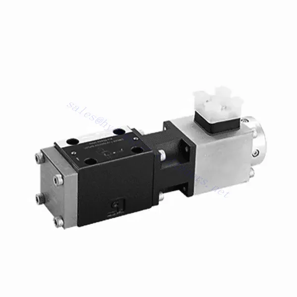
DBE6X(E) Series Proportional Pressure Relief Hydraulic Valve
Como um dos fabricantes, fornecedores e exportadores de produtos mecânicos de cilindros hidráulicos, oferecemos cilindros hidráulicos e muitos outros produtos.
Entre em contato conosco para obter detalhes.
Correio eletrônico:sales@hydraulic-cylinders.net
Fabricante, fornecedor e exportador de cilindros hidráulicos.
DBE6X(E) Series Proportional Pressure Relief Hydraulic Valve
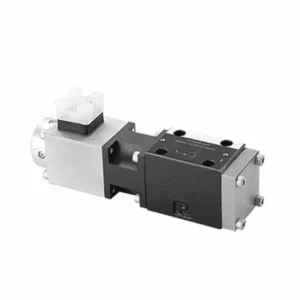
The DBE6X(E) series proportional pressure relief hydraulic Valve is a cutting-edge component that provides accurate and dynamic pressure control in hydraulic systems. With its advanced proportional control technology, this valve ensures optimal performance, efficiency, and safety.
The DBETX series proportional pressure relief hydraulic valve empowers hydraulic systems with precise pressure control, enhanced efficiency, and equipment protection. With its commensurate pressure relief capabilities, this valve ensures optimal performance across various applications. By following the recommended usage methods and maintenance guidelines, you can maximize the benefits and reliability of the DBETX series valve, elevating the performance and control of your hydraulic system. Upgrade your hydraulic setup today and experience superior pressure regulation with the DBETX series proportional pressure relief hydraulic valve.
DBE6X(E) Series Proportional Pressure Relief Hydraulic Valve Key Characteristics:
- Proportional Pressure Relief:
- The DBE6X(E) series valve offers precise and proportional pressure relief, allowing dynamic hydraulic pressure control.
- It ensures accurate pressure regulation in response to varying load conditions, preventing system overload and safeguarding hydraulic components.
- Eficiência aprimorada do sistema:
- This valve enables precise hydraulic pressure control, resulting in enhanced system efficiency and reduced energy consumption.
- By maintaining the desired pressure levels, it minimizes pressure fluctuations, optimizes system performance, and reduces operational costs.
- Safety and Equipment Protection:
- The DBE6X(E) Series Valve acts as a protective mechanism by limiting the pressure within the hydraulic system, safeguarding equipment and operators.
- It prevents excessive pressure build-up, reducing the risk of component damage, system failures, and potential accidents.
- Proportional Control Functionality:
- With its proportional control technology, the DBE6X(E) series valve offers smooth and precise pressure adjustment.
- It allows for real-time pressure control, enabling seamless integration into various hydraulic systems and applications.
DBE6X(E) Series Proportional Pressure Relief Hydraulic Valve Parameter:
| Em geral | ||||||
| Construção | Pilot stage | Poppet valve | ||||
| Main stage | Spool valve | |||||
| Actuation | Proportional solenoid without position control, external amplifier | |||||
| Connection type | Subplate, mounting hole configuration NG6 (SIO 4401-03-02-094) | |||||
| Posição de instalação | Opcional | |||||
| Circunstâncias faixa de temperatura | °C | -20 to +50 | ||||
| Peso | Kg | 2.2 | ||||
| Vibration resistance, test condition | Max. 25 g, shaken in 3 dimensions (24 h) | |||||
| Hydraulic ( measured with HLP 46, oil = 40℃ ±5℃ ): | ||||||
| Fluido de pressão | Hydraulic oil to DIN 51524…535,other fluids after prior consultation | |||||
| Faixa de viscosidade | recommended | mm²/s | 20…100 | |||
| max. permitted | mm²/s | 10…800 | ||||
| Pressure fluid temperature range | °C | -20 to +80 | ||||
| Maximum permitted degree of contamination of pressure fluid Purity class to ISO 4406 (c) | Class 18/16/13 | |||||
| Direction of flow | See symbol | |||||
| Max. setting pressure (at Qmaxx = 1 L/min) | bar | 80 | 180 | 250 | 315 | |
| Min. settable pressure(当 Qmin = 1 L/min) | bar | 7 | 8 | 9 | 10 | |
| Pressão máxima de operação | bar | Port P:315 | ||||
| Port T:250 | ||||||
| Max. mechanical pressure limitation level,e.g. when solenoid current I>Imax | bar | < 90 | < 190 | < 260 | < 235 | |
| Pilot oil flow | L/min | cerca de 0,6 | ||||
| Taxa de fluxo máxima | L/min | 40 | ||||
| Dados elétricos | ||||||
| Fator de duração cíclica | % | 100 ED | ||||
| Degree of protection | IP 65 to DIN 40050 and IEC 14434/5 | |||||
| Solenoid connection | Plug-in connector to DIN 43650/ISO 4400,M16X1.5(2P+PE) | |||||
| Valve with solenoid type | 0.8A | 2.5A | ||||
| Corrente máxima do solenóide | Imax | 0.8A | 2.5A | |||
| Coil resistance R20 | Ω | 22 | 3 | |||
| Max. power consumption at 100% load and operating temperature | VA | 25 | 30 | |||
| Static/Dynamic | ||||||
| Histerese | % | ≤ 4 | ||||
| Range of inversion | % | ≤3 | ||||
| Manufacturing tolerance for Pmax | % | ≤10 | ||||
| Response time 100% signal change | EM | On 200 / Off | ||||
DBE6X(E) Series Proportional Pressure Relief Hydraulic Valve Advantages:
• Pilot valve to restrict system pressure (control oil internal only)
• Can adjust by controlling the coil current according to the characteristic curve and the selected electronic control unit
• Solenoid type Imax=0.8 A or 2.5 A
• In the event of electronic control unit failure, the overload protection can function to the highest degree (coil current > Imax)
• Used in valve sub-plate mounting, installation hole follows ISO 441-03-02-0-94,
• Cable sockets follows DIN 43650-AM2
• External electronic control unit with ramp and valve adjustment function VT-SSPA1-508/525-L2X/V0/*
Usage Method Of DBE6X(E) Series Proportional Pressure Relief Hydraulic Valve:
- Avaliação do Sistema:
- Avalie seu sistema hidráulico e identifique os requisitos específicos de controle de pressão.
- Determine if the DBE6X(E) series valve is compatible with your system based on its pressure range, flow capacity, and other specifications.
- Seleção de válvulas:
- Choose the appropriate DBE6X(E) series valve variant based on your system parameters, pressure range, and flow requirements.
- Considere a classificação de pressão máxima, o tempo de resposta e as condições operacionais.
- Instalação:
- Siga cuidadosamente as instruções de instalação do fabricante, garantindo o alinhamento adequado e a montagem segura da válvula.
- Conecte a válvula ao sistema hidráulico, garantindo conexões sem vazamentos e alinhamento adequado da direção do fluxo.
- Ajuste de pressão:
- Utilize the proportional control signal or adjustment mechanism provided with the DBE6X(E) series valve to set the desired pressure relief level.
- Ajuste a válvula incrementalmente, monitorando as leituras do manômetro e a resposta do sistema para obter um controle preciso da pressão.
How To Adjust Hydraulic Flow Control Valve?
Adjusting a hydraulic pressure relief valve allows you to set the desired maximum pressure in a hydraulic system. This is important for maintaining system integrity and preventing damage to components. Here’s a step-by-step guide on how to adjust a hydraulic pressure relief valve:
- Identify the Pressure Relief Valve:
- Locate the pressure relief valve in your hydraulic system. It is typically installed in the hydraulic line and often near the pump or control valve.
- Understand the Valve Design:
- Familiarize yourself with the specific design of the pressure relief valve you are working with. Different valves may have varying adjustment mechanisms, such as a knob, screw, or locknut.
- Determine a pressão desejada:
- Assess the requirements of your hydraulic system and determine the desired maximum pressure. This will guide you in adjusting the pressure relief valve accurately.
- Prepare o sistema:
- Before making any adjustments, shut off the hydraulic system and relieve the pressure by moving the control levers back and forth or following the manufacturer’s recommended procedure.
- Locate the Adjustment Mechanism:
- Identify the adjustment mechanism on the pressure relief valve. It could be a knob, screw, or locknut positioned on the valve body or adjacent to it.
- Adjust the Valve:
- If the valve has a knob or handle, turn it clockwise to increase the pressure relief setting or counterclockwise to decrease it. If the valve has a screw, turn it clockwise to increase the pressure relief or counterclockwise to decrease it.
- Faça ajustes incrementais:
- When adjusting the pressure relief valve, make small, incremental changes to avoid sudden or drastic variations in pressure. This allows you to fine-tune the maximum pressure and achieve the desired performance.
- Observe the System:
- With each adjustment, observe the hydraulic system and its components. Pay attention to the pressure gauge readings to see if they align with the desired maximum pressure.
- Teste e verifique:
- Operate the hydraulic system and monitor the pressure to ensure that it remains within the desired range. Check for any pressure fluctuations or irregularities that may indicate the need for further adjustment.
- Bloqueie o ajuste:
- Once you have achieved the desired pressure relief setting, secure the adjustment mechanism to prevent unintended changes. Some valves may have a locking nut or set screw that can be tightened to hold the adjustment in place.
- Monitor and Revisit:
- Regularly monitor the pressure relief valve and the hydraulic system. If there are changes in the system or if the desired maximum pressure needs to be adjusted, revisit the pressure relief valve and repeat the adjustment process as needed.
Aptidão e capacidade da fábrica:
(1) Montagem
Temos uma plataforma de montagem de pesquisa e desenvolvimento independente de primeira classe. A oficina de produção de cilindros hidráulicos tem quatro linhas de montagem semiautomáticas de cilindros de elevação e uma linha de montagem automática de cilindros de inclinação, com uma capacidade de produção anual projetada de 1 milhão de peças. A oficina de cilindros especiais é equipada com várias especificações de um sistema de montagem de limpeza semiautomática com uma capacidade de produção anual projetada de 200.000 peças e equipada com famosos equipamentos de usinagem CNC, um centro de usinagem, um equipamento especial de processamento de cilindros de alta precisão, uma máquina de solda robotizada, uma máquina de limpeza automática, uma máquina de montagem automática de cilindros e uma linha de produção de pintura automática. O equipamento crítico existente é de mais de 300 conjuntos (conjuntos). A alocação ideal e o uso eficiente dos recursos do equipamento garantem os requisitos de precisão dos produtos e atendem às necessidades de alta qualidade dos produtos.


(2) Usinagem
A oficina de usinagem é equipada com um centro de torneamento de trilho inclinado personalizado, um centro de usinagem, uma máquina de brunimento de alta velocidade, um robô de soldagem e outros equipamentos relacionados, que podem lidar com o processamento de tubos de cilindros com diâmetro interno máximo de 400 mm e comprimento máximo de 6 metros.

(3) Soldagem

(4) Pintura e revestimento
Com linhas de revestimento de tinta à base de água automáticas de cilindros de pequeno e médio porte, para obter carregamento e descarregamento automáticos de robôs e pulverização automática, a capacidade projetada é de 4.000 peças por turno;
Também temos uma linha de produção de tinta semiautomática para cilindros grandes, acionada por uma corrente elétrica, com capacidade de projeto de 60 caixas por turno.


(5) Testes
Temos instalações de inspeção e bancos de teste de primeira classe para garantir que o desempenho do cilindro atenda aos requisitos.

Somos um dos melhores fabricantes de cilindros hidráulicos. Oferecemos cilindros hidráulicos completos. Também fornecemos os correspondentes caixas de câmbio agrícolas. Exportamos nossos produtos para clientes em todo o mundo e conquistamos uma boa reputação devido à qualidade superior de nossos produtos e ao serviço pós-venda. Convidamos clientes nacionais e estrangeiros a entrar em contato conosco para negociar negócios, trocar informações e cooperar conosco!
Cilindro hidráulico Aplicação:
