

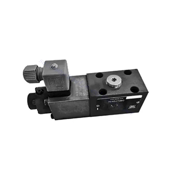
DBET(E) Series Proportional Pressure Relief Hydraulic Valve
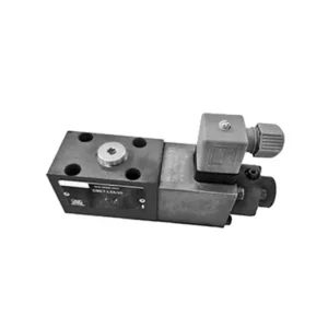

The DBET(E) series proportional pressure relief hydraulic valve is a cutting-edge component designed to deliver precise pressure control in hydraulic systems. With its advanced proportional control technology and exceptional performance, this valve optimizes system efficiency, enhances safety, and prolongs the lifespan of hydraulic equipment.
The DBET(E) series proportional pressure relief hydraulic valve is an indispensable component for achieving precise pressure control in hydraulic systems. With its proportional pressure regulation, enhanced efficiency, and equipment protection features, this valve optimizes system performance while ensuring the safety and longevity of hydraulic equipment. By following the recommended usage methods and maintenance guidelines, you can harness the full potential of the DBET(E) series proportional pressure relief hydraulic valve, maximizing the performance and reliability of your hydraulic system. Upgrade your hydraulic setup today and experience optimal pressure control with the DBET(E) series valve.
DBET(E) Series Proportional Pressure Relief Hydraulic Valve Key Characteristics:
- Controle de pressão proporcional:
- The DBET(E) series valve offers precise and proportional pressure relief, allowing for accurate and dynamic pressure regulation in hydraulic systems.
- It maintains a consistent pressure level against varying loads, ensuring optimal performance and preventing damage to hydraulic components.
- Eficiência aprimorada do sistema:
- By providing proportional pressure control, this valve helps optimize system efficiency by reducing energy consumption and minimizing pressure fluctuations.
- It ensures that hydraulic equipment operates at the desired pressure, resulting in improved productivity and reduced operational costs.
- Safety and Equipment Protection:
- The DBET(E) Series Valve acts as a safety measure by limiting the pressure within the hydraulic system, preventing overloading and potential damage to equipment or operators.
- It safeguards sensitive components from excessive pressure, extending their lifespan and reducing the risk of system failures.
- Flexibility and Adaptability:
- This valve is available in different sizes and pressure ranges, allowing for compatibility with various hydraulic systems and applications.
- Its adaptable design makes it suitable for various industries, including manufacturing, construction, agriculture, and more.
DBET(E) Series Proportional Pressure Relief Hydraulic Valve Parameter:
| Fluido | Óleo mineral adequado para vedação NBR e FKM | |
| Éster de fosfato para selo FKM | ||
| Faixa de temperatura do fluido | °C | -30 a +80 (vedações NBR) |
| -20 to +80 (FKM seals) | ||
| Faixa de viscosidade | milímetros2/s | 15 to 380 |
| Grau de contaminação | Maximum permissible degree of fluid contamination: Class 9 and ISO4406 Class 20/18/15 | |
| Max. operating pressure (Port P) | bar | 350 |
| Pressão máxima de ajuste | bar | 50; 100; 200; 315; 350 |
| Pressão mínima ajustável | Veja as curvas características. | |
| Pressão mínima ajustável no valor de comando 0 | =Pressão mínima ajustável | |
| Return pressure(Port T) | bar | Separate and at zero pressure to tank |
| Taxa de fluxo máxima | L/min | 2 |
| Linearidade | ± 3.5 % of max. settable pressure | |
| Histerese | ± 1.5 % of max. settable pressure | |
| Repetibilidade | < ± 2 % of max. settable pressure | |
| Tempo de comutação | EM | 30 to 150 (system dependent) |
DBET(E) Series Proportional Pressure Relief Hydraulic Valve Advantages:
• Direct, to restrict system pressure
• Installation face follows ISO 4401-03-02-0-05
• Cinco faixas de pressão
• Accompanying electronic amplifier VT-2000 or plugin amplifier VT-SSPA1-…-L2X (separate order)
Usage Method Of DBET(E) Series Proportional Pressure Relief Hydraulic Valve :
- Avaliação do Sistema:
- Assess the specific requirements of your hydraulic system, including the desired pressure range, maximum flow rate, and compatibility with existing components.
- Determine if the DBET(E) series valve suits your application based on its pressure control capabilities and compatibility with your system.
- Seleção de válvulas:
- Choose the appropriate variant of the DBET(E) series valve based on your system parameters, required pressure range, and flow capacity.
- Considere a classificação de pressão máxima, o tempo de resposta e as condições operacionais.
- Instalação:
- Follow the manufacturer’s installation instructions carefully, ensuring proper alignment and secure valve mounting.
- Connect the valve to the hydraulic system, paying attention to the flow direction indicators and ensuring leak-free connections.
- Configuração de pressão:
- Adjust the pressure relief setting of the valve to match the desired pressure range for your application.
- This can typically be achieved through proportional control signals or adjustments on the valve itself, depending on the specific model.
Como adicionar uma válvula hidráulica a um trator?
Adjusting a hydraulic flow control valve allows you to regulate the speed or flow rate of hydraulic fluid in a hydraulic system. By controlling the flow, you can optimize the performance of hydraulic cylinders, motors, or other hydraulic components. Here’s a step-by-step guide on how to adjust a hydraulic flow control valve:
- Identify the Flow Control Valve:
- Locate the flow control valve in your hydraulic system. It is typically installed in the hydraulic line leading to the component you want to control, such as a cylinder or motor.
- Understand the Valve Design:
- Familiarize yourself with the specific design of the flow control valve you are working with. Different valves may have varying adjustment mechanisms, such as a knob, screw, or handle.
- Determine the Desired Flow Rate:
- Assess the requirements of your hydraulic system and determine the desired flow rate or speed for the component you are controlling. This will guide you in adjusting the flow control valve accurately.
- Prepare o sistema:
- Before making any adjustments, shut off the hydraulic system and relieve the pressure by moving the control levers back and forth or following the manufacturer’s recommended procedure.
- Locate the Adjustment Mechanism:
- Identify the adjustment mechanism on the flow control valve. It could be a knob, screw, or handle positioned on the valve body or adjacent to it.
- Adjust the Valve:
- If the valve has a knob or handle, turn it clockwise to decrease the flow rate or counterclockwise to increase the flow rate. If the valve has a screw, turn it clockwise to reduce the flow or counterclockwise to increase it.
- Faça ajustes incrementais:
- When adjusting the flow control valve, make small, incremental changes to avoid sudden or drastic variations in flow rate. This allows you to fine-tune the speed and achieve the desired performance.
- Observe the System:
- With each adjustment, observe the hydraulic system and the component being controlled. Pay attention to the speed or flow rate to see if it aligns with the desired outcome.
- Test and Refine:
- Operate the hydraulic system and the controlled component to test the effectiveness of your adjustments. If necessary, continue making incremental changes until the desired flow rate or speed is achieved.
- Bloqueie o ajuste:
- Once you have achieved the desired flow rate, secure the adjustment mechanism to prevent unintended changes. Some valves may have a locking nut or set screw that can be tightened to hold the adjustment in place.
- Monitor and Revisit:
- Regularly monitor the performance of the hydraulic system and the controlled component. If there are changes in the system or if the desired flow rate needs to be adjusted, revisit the flow control valve and repeat the adjustment process as needed.
Aptidão e capacidade da fábrica:
(1) Montagem
Temos uma plataforma de montagem de pesquisa e desenvolvimento independente de primeira classe. A oficina de produção de cilindros hidráulicos tem quatro linhas de montagem semiautomáticas de cilindros de elevação e uma linha de montagem automática de cilindros de inclinação, com uma capacidade de produção anual projetada de 1 milhão de peças. A oficina de cilindros especiais é equipada com várias especificações de um sistema de montagem de limpeza semiautomática com uma capacidade de produção anual projetada de 200.000 peças e equipada com famosos equipamentos de usinagem CNC, um centro de usinagem, um equipamento especial de processamento de cilindros de alta precisão, uma máquina de solda robotizada, uma máquina de limpeza automática, uma máquina de montagem automática de cilindros e uma linha de produção de pintura automática. O equipamento crítico existente é de mais de 300 conjuntos (conjuntos). A alocação ideal e o uso eficiente dos recursos do equipamento garantem os requisitos de precisão dos produtos e atendem às necessidades de alta qualidade dos produtos.


(2) Usinagem
A oficina de usinagem é equipada com um centro de torneamento de trilho inclinado personalizado, um centro de usinagem, uma máquina de brunimento de alta velocidade, um robô de soldagem e outros equipamentos relacionados, que podem lidar com o processamento de tubos de cilindros com diâmetro interno máximo de 400 mm e comprimento máximo de 6 metros.


(3) Soldagem


(4) Pintura e revestimento
Com linhas de revestimento de tinta à base de água automáticas de cilindros de pequeno e médio porte, para obter carregamento e descarregamento automáticos de robôs e pulverização automática, a capacidade projetada é de 4.000 peças por turno;
Também temos uma linha de produção de tinta semiautomática para cilindros grandes, acionada por uma corrente elétrica, com capacidade de projeto de 60 caixas por turno.


(5) Testes
Temos instalações de inspeção e bancos de teste de primeira classe para garantir que o desempenho do cilindro atenda aos requisitos.


Somos um dos melhores fabricantes de cilindros hidráulicos. Oferecemos cilindros hidráulicos completos. Também fornecemos os correspondentes caixas de câmbio agrícolas. Exportamos nossos produtos para clientes em todo o mundo e conquistamos uma boa reputação devido à qualidade superior de nossos produtos e ao serviço pós-venda. Convidamos clientes nacionais e estrangeiros a entrar em contato conosco para negociar negócios, trocar informações e cooperar conosco!