

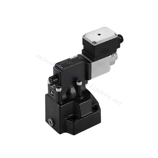
DRE(E) Series Proportional Pressure Reducing Hydraulic Valve
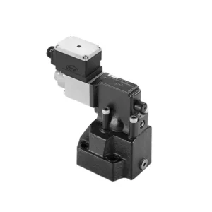

The DRE(E) series proportional pressure-reducing hydraulic valve is a cutting-edge hydraulic component that provides precise pressure control in hydraulic systems. With its advanced proportional control technology, this valve ensures optimal performance, efficiency, and safety.
The DRE(E) series proportional pressure-reducing hydraulic valve empowers hydraulic systems with precise pressure control, enhanced efficiency, and equipment protection. With its advanced proportional control technology, this valve ensures optimal performance across various applications. By following the recommended usage methods and maintenance guidelines, you can maximize the benefits and reliability of the DRE(E) series valve, elevating the pressure control and overall performance of your hydraulic system. Upgrade your hydraulic setup today and experience superior pressure regulation with the DRE(E) series proportional pressure-reducing hydraulic valve.
DRE(E) Series Proportional Pressure Reducing Hydraulic Valve Key Characteristics:
- Proportional Pressure Reduction:
- The DRE(E) series valve offers precise and proportional pressure reduction, enabling dynamic hydraulic pressure control.
- It ensures accurate pressure regulation, maintaining a consistent and safe pressure level within the hydraulic system.
- Eficiência aprimorada do sistema:
- This valve enables precise hydraulic pressure control, resulting in enhanced system efficiency and reduced energy consumption.
- By maintaining the desired pressure levels, it minimizes pressure fluctuations, optimizes system performance, and lowers operational costs.
- Safety and Equipment Protection:
- The DRE(E) series valve acts as a protective mechanism by limiting the pressure within the hydraulic system, safeguarding equipment and operators.
- It prevents excessive pressure build-up, reducing the risk of component damage, system failures, and potential accidents.
- Proportional Control Functionality:
- With its proportional control technology, the DRE(E) series valve offers smooth and precise pressure adjustment.
- It allows for real-time pressure control, enabling seamless integration into various hydraulic systems and applications.
DRE(E) Series Proportional Pressure Reducing Hydraulic Valve Parameter:
| Em geral | ||||
| Fluido | Óleo mineral adequado para vedação NBR e FKM | |||
| Éster de fosfato para selo FKM | ||||
| Faixa de temperatura do fluido | °C | -30 a +80 (vedações NBR) | ||
| -20 a +80 (vedações FKM) | ||||
| Faixa de viscosidade | milímetros2/s | 2,8 a 380 | ||
| Grau de contaminação | Grau máximo permitido de contaminação do fluido: Classe 9. NAS 1638 ou 20/18/15, ISO4406 | |||
| Pressão máxima de operação | 315 bar | |||
| Porta A, B e X | bar | 50; 100; 200; 315 | ||
| Pressão máxima de ajuste | bar | Em relação ao fluxo (Q), veja as curvas características | ||
| Pressão mínima ajustável | =Pressão mínima ajustável | |||
| Pressão mínima ajustável no valor de comando 0 | Separado e com pressão zero para tanques | |||
| Porta de pressão de óleo de retorno Y | bar | Pressão de ajuste | Faixa de pressão sob pressão máxima de segurança | |
| Segurança de pressão máxima (infinitamente ajustável) | 50 bar | 10-60+20 bar | ||
| 100 bar | 10-120+20 bar | |||
| 200 bar | 10-220+20 bar | |||
| 315 bar | 10-340+20 bar | |||
| Condição de ajuste de segurança de pressão máxima | When rated pressure is 50 bar, between 60 bar and 80 bar | |||
| When rated pressure is 100 bar, between120 bar and 140 bar | ||||
| When rated pressure is 200 bar, between 220 bar and 240 bar | ||||
| When rated pressure is 315 bar, between 340 bar and 360 bar | ||||
| Tamanho | 10 | 25 | 32 | |
| Taxa de fluxo máxima | 200 | 400 | 600 | |
| Óleo piloto (para válvula piloto)) | L/min | 0,7 a 2 | ||
| Linearidade | L/min | ±3,5% | ||
| Repetibilidade | <±2% | |||
| Histerese | com shimmy | sem trepidação | ||
| ±1,5% P máx. (200Hz, amplitude 200mAsss) | ±4,5% P máx. | |||
| Tempo de comutação | 30~150ms(independent with the system) | |||
| Dados elétricos | ||||
| Poder | DC | |||
| Corrente mínima do solenóide | mA | 100 | ||
| Corrente máxima do solenóide | mA | 800 | ||
| Resistência da bobina | 19.5Ω at 20℃, Max. warm value: 28.8Ω | |||
| Situação de trabalho | Contínuo | |||
| Faixa máxima de temperatura ambiente | +50℃ | |||
| Conexão elétrica | Conector plug-in conforme DIN 43 650/2 +SL/PG11 | |||
| Isolamento conforme DIN 40 050 | IP 65 | |||
| Amplifier | VT2000 | |||
DRE(E) Series Proportional Pressure Reducing Hydraulic Valve Advantages:
• Usado para montagem de subplaca inferior
• Instalação frontal conforme DIN24340 E e ISO 6264
• Usado na instalação de blocos de caminho de óleo
• Quatro faixas de pressão
• Estrutura de proteção de pressão máxima (opcional)
• Amplificador eletrônico correspondente tipo VT-2000 (deve ser pedido separadamente)
Usage Method Of DRE(E) Series Proportional Pressure Reducing Hydraulic Valve:
- Avaliação do Sistema:
- Avalie seu sistema hidráulico e identifique os requisitos específicos de controle de pressão.
- Determine if the DRE(E) series valve is compatible with your system based on its pressure range, flow capacity, and other specifications.
- Seleção de válvulas:
- Choose the appropriate DRE(E) series valve variant based on your system parameters, pressure range, and flow requirements.
- Considere a classificação de pressão máxima, o tempo de resposta e as condições operacionais.
- Instalação:
- Follow the manufacturer’s installation instructions carefully, ensuring proper alignment and secure valve mounting.
- Conecte a válvula ao sistema hidráulico, garantindo conexões sem vazamentos e alinhamento adequado da direção do fluxo.
- Ajuste de pressão:
- Utilize the proportional control signal or adjustment mechanism provided with the DRE(E) series valve to set the desired pressure reduction level.
- Ajuste a válvula incrementalmente, monitorando as leituras do manômetro e a resposta do sistema para obter um controle preciso da pressão.
How To Adjust Hydraulic Pressure Relief Valve?
Adjusting a hydraulic pressure relief valve allows you to regulate the maximum pressure within a hydraulic system. This is important for maintaining system integrity and preventing damage to components. Here’s a step-by-step guide on how to adjust a hydraulic pressure relief valve:
- Identify the Pressure Relief Valve:
- Locate the hydraulic pressure relief valve in your system. It is typically positioned in the hydraulic line or integrated into a manifold block.
- Understand the Valve Design:
- Familiarize yourself with the specific design of the pressure relief valve you are working with. Different valves may have varying adjustment mechanisms, such as a knob, screw, or locknut.
- Determine the Desired Pressure Setting:
- Assess the requirements of your hydraulic system and determine the desired maximum pressure. Consider the system’s specifications, load conditions, and safety limits.
- Prepare o sistema:
- Before making any adjustments, shut off the hydraulic system and relieve the pressure by moving the control levers back and forth or following the manufacturer’s recommended procedure.
- Locate the Adjustment Mechanism:
- Identify the adjustment mechanism on the pressure relief valve. It could be a knob, screw, or locknut positioned on the valve body or adjacent to it.
- Adjust the Valve:
- If the valve has a knob or handle, turn it clockwise to increase the pressure relief setting or counterclockwise to decrease it. If the valve has a screw, turn it clockwise to increase the ground or counterclockwise to drop it.
- Faça ajustes incrementais:
- When adjusting the pressure relief valve, make small, incremental changes to avoid sudden or drastic variations in pressure. This allows you to fine-tune the system and prevent potential damage.
- Observe the System:
- With each adjustment, observe the hydraulic system’s pressure gauge or indicator to see the effect of the changes. Ensure that the pressure stays within the desired range.
- Teste e verifique:
- Gradually increase the system’s pressure and monitor the pressure relief valve’s response. Ensure it relieves stress when the maximum set pressure is reached and maintains the desired maximum pressure.
- Bloqueie o ajuste:
- Once you have achieved the desired pressure setting, secure the adjustment mechanism to prevent unintended changes. Some valves may have a locking nut or set screw that can be tightened to hold the adjustment in place.
- Document the Adjustment:
- Keep a record of the adjusted pressure relief setting for future reference and maintenance purposes. This documentation will help maintain consistency and aid troubleshooting efforts.
Aptidão e capacidade da fábrica:
(1) Montagem
Temos uma plataforma de montagem de pesquisa e desenvolvimento independente de primeira classe. A oficina de produção de cilindros hidráulicos tem quatro linhas de montagem semiautomáticas de cilindros de elevação e uma linha de montagem automática de cilindros de inclinação, com uma capacidade de produção anual projetada de 1 milhão de peças. A oficina de cilindros especiais é equipada com várias especificações de um sistema de montagem de limpeza semiautomática com uma capacidade de produção anual projetada de 200.000 peças e equipada com famosos equipamentos de usinagem CNC, um centro de usinagem, um equipamento especial de processamento de cilindros de alta precisão, uma máquina de solda robotizada, uma máquina de limpeza automática, uma máquina de montagem automática de cilindros e uma linha de produção de pintura automática. O equipamento crítico existente é de mais de 300 conjuntos (conjuntos). A alocação ideal e o uso eficiente dos recursos do equipamento garantem os requisitos de precisão dos produtos e atendem às necessidades de alta qualidade dos produtos.


(2) Usinagem
A oficina de usinagem é equipada com um centro de torneamento de trilho inclinado personalizado, um centro de usinagem, uma máquina de brunimento de alta velocidade, um robô de soldagem e outros equipamentos relacionados, que podem lidar com o processamento de tubos de cilindros com diâmetro interno máximo de 400 mm e comprimento máximo de 6 metros.


(3) Soldagem


(4) Pintura e revestimento
Com linhas de revestimento de tinta à base de água automáticas de cilindros de pequeno e médio porte, para obter carregamento e descarregamento automáticos de robôs e pulverização automática, a capacidade projetada é de 4.000 peças por turno;
Também temos uma linha de produção de tinta semiautomática para cilindros grandes, acionada por uma corrente elétrica, com capacidade de projeto de 60 caixas por turno.


(5) Testes
Temos instalações de inspeção e bancos de teste de primeira classe para garantir que o desempenho do cilindro atenda aos requisitos.


Somos um dos melhores fabricantes de cilindros hidráulicos. Oferecemos cilindros hidráulicos completos. Também fornecemos os correspondentes caixas de câmbio agrícolas. Exportamos nossos produtos para clientes em todo o mundo e conquistamos uma boa reputação devido à qualidade superior de nossos produtos e ao serviço pós-venda. Convidamos clientes nacionais e estrangeiros a entrar em contato conosco para negociar negócios, trocar informações e cooperar conosco!