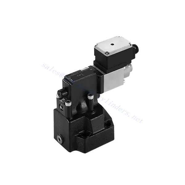
DRE(E) Series Proportional Pressure Reducing Valve
Como um dos fabricantes, fornecedores e exportadores de produtos mecânicos de cilindros hidráulicos, oferecemos cilindros hidráulicos e muitos outros produtos.
Entre em contato conosco para obter detalhes.
Correio eletrônico:sales@hydraulic-cylinders.net
Fabricante, fornecedor e exportador de cilindros hidráulicos.
DRE(E) Series Proportional Pressure Reducing Valve
The DRE(E) series proportional pressure reducing valve is a state-of-the-art hydraulic component that delivers precise and reliable pressure control in various industrial applications. With its advanced features, exceptional performance, and robust construction, this valve offers a solution that optimizes system efficiency and enhances productivity.
The DRE(E) series proportional pressure reducing valve offers precise and reliable pressure control for hydraulic systems. With exceptional proportional control, pressure reduction function, high flow capacity, and fast response time, this valve provides accurate pressure regulation and safeguards downstream components. By following the recommended usage methods and maintenance guidelines, you can harness the full potential of this valve and achieve enhanced performance in your hydraulic applications. Upgrade your hydraulic system today with the DRE(E) series proportional pressure reducing valve and experience optimal pressure control with precision and reliability.
DRE(E) Series Proportional Pressure Reducing Valve Key Characteristics:
- Controle Proporcional:
- The DRE(E) series valve boasts exceptional proportional control capabilities, enabling precise adjustment of pressure levels.
- This advanced control feature ensures accurate pressure regulation tailored to specific system requirements, promoting efficient and optimized performance.
- Pressure Reduction Function:
- Equipped with a pressure reduction function, this valve efficiently lowers the incoming pressure to a predefined setpoint.
- By accurately reducing the pressure, the valve protects downstream components, preventing damage and ensuring stable system operation.
- Alta capacidade de fluxo:
- The DRE(E) series valve is designed to handle high flow rates, making it suitable for applications that require substantial fluid volumes.
- Its high flow capacity enables efficient operation even in demanding industrial environments.
- Tempo de resposta rápido:
- With an impressive response time, this valve allows for rapid adjustments to pressure changes within the system.
- The fast response ensures precise control, minimizing pressure fluctuations and promoting stable and consistent system performance.
DRE(E) Series Proportional Pressure Reducing Valve Parameter:
| Em geral | |||||
| Fluido | Óleo mineral adequado para vedação NBR e FKM | ||||
| Éster de fosfato para selo FKM | |||||
| Faixa de temperatura do fluido | °C | -30 a +80 (vedação NBR) | |||
| -20 a +80 (selo FKM) | |||||
| Faixa de viscosidade | milímetros2/s | 2,8 a 380 | |||
| Grau de contaminação | Grau máximo permitido de contaminação do fluido: Classe 9. NAS 1638 ou 20/18/15, ISO4406 | ||||
| Pressão máxima de operação | Port A,B | bar | 315 | ||
| Porto Y | Separate and at zero pressure to tank | ||||
| Pressão máxima de ajuste | Porto A | bar | 50; 100; 200; 315 | ||
| Pressão mínima ajustável | Porto A | Em relação ao fluxo (Q), veja as curvas características | |||
| Pressure at current value 0 in port A | =Min. settable pressure (Refer to the characteristic curve ) | ||||
| Segurança de pressão máxima (infinitamente ajustável) | Pressão de ajuste | Faixa de pressão sob pressão máxima de segurança | |||
| 50 bar | 10-60+20 bar | ||||
| 100 bar | 10-120+20 bar | ||||
| 200 bar | 10-220+20 bar | ||||
| 315 bar | 10-340+20 bar | ||||
| Condição de ajuste de segurança de pressão máxima | When rated pressure=50 bar, between 60~80 bar | ||||
| When rated pressure=100 bar, between 120~140 bar | |||||
| When rated pressure=200 bar, between 220~240 bar | |||||
| When rated pressure=315 bar, between 340~360 bar | |||||
| Tamanho | 10 | 25 | 32 | ||
| Taxa de fluxo máxima | L/min | 80 | 200 | 300 | |
| Pilot flow-rate (for pilot valve) | L/min | 0,7 a 2 | |||
| Linearidade | ±3,5% | ||||
| Repetibilidade | <±2% | ||||
| Histerese | com shimmy | sem trepidação | |||
| ±2.5% Pmax( 200Hz, amplitude 200mAsss) | ±4.5% Pmax | ||||
| Tempo de comutação | 100 to 300ms (undependent with the system) | ||||
| Dados elétricos | |||||
| Poder | DC | ||||
| Corrente mínima do solenóide | mA | 100 | |||
| Corrente máxima do solenóide | mA | 800 | |||
| Resistência da bobina | 19.5Ω at 20℃, Max. warm value :28.8Ω | ||||
| Situação de trabalho | Contínuo | ||||
| Max. ambient temperature range | +50℃ | ||||
| Conexão elétrica | Plug-in connector to DIN 43650/2+SL/PG11 | ||||
| Isolamento conforme DIN 40 050 | IP 65 | ||||
| Amplificador | VT2000 | ||||
DRE(E) Series Proportional Pressure Reducing Valve Advantages:
• Usado para montagem de subplaca inferior
• Installation face follow DIN 24340 D and ISO 5781
• Usado na instalação de blocos de caminho de óleo
• Quatro faixas de pressão
• Estrutura de proteção de pressão máxima (opcional)
• Amplificador eletrônico correspondente tipo VT-2000 (deve ser pedido separadamente)
Usage Method Of DRE(E) Series Proportional Pressure Reducing Valve :
- Avaliação do Sistema:
- Evaluate your hydraulic system’s requirements, considering flow rate, pressure range, and system dynamics.
- Determine whether the proportional pressure control offered by the DRE(E) series valve aligns with your system’s needs.
- Seleção de válvulas:
- Select the appropriate variant of the DRE(E) series valve based on your system parameters and performance requirements.
- Considere fatores como capacidade de fluxo, faixa de pressão e compatibilidade com outros componentes do sistema para garantir a funcionalidade ideal.
- Instalação:
- Siga cuidadosamente as instruções de instalação do fabricante para garantir o posicionamento correto e a montagem segura da válvula.
- Posicione a válvula corretamente dentro do sistema hidráulico, considerando fatores como direção do fluxo do fluido e acessibilidade para manutenção.
- Configuração de pressão:
- Set the desired pressure level by adjusting the valve’s control mechanism according to the manufacturer’s guidelines.
- Certifique-se de que o ponto de ajuste esteja alinhado com os requisitos específicos do seu sistema.
How To Remove A Shower Valve Cartridge?
Removing a shower valve cartridge may vary depending on the specific model and manufacturer. However, here is a general step-by-step guide that can help you remove a shower valve cartridge:
- Turn off the Water Supply: Locate the main water shut-off valve for your shower and turn it off to cut off the water supply. This step is essential to prevent any water flow while you work on removing the cartridge.
- Remove the Shower Handle: Most shower handles have a screw or decorative cap at the base. Look for this screw or cap and remove it using a screwdriver or by gently prying it off. Once removed, take off the handle by pulling it straight out.
- Access the Cartridge: Depending on the type of shower valve you have, you may need to remove additional parts to access the cartridge. This can include a trim plate or escutcheon that covers the valve. Use a screwdriver to remove any screws holding these parts in place and gently pull them away.
- Remove the Retaining Clip or Nut: Look for a retaining clip or nut that holds the cartridge in place. This clip or nut is usually located on the top of the cartridge and secures it to the valve body. Use pliers or an adjustable wrench to loosen and remove the clip or nut.
- Remove the Cartridge: Once the retaining clip or nut is removed, you can proceed to pull out the cartridge. Grip the cartridge firmly and pull it straight out of the valve body. If it is stuck, you may need to wiggle it gently or use a cartridge removal tool specific to your shower valve model.
- Limpar e inspecionar: With the cartridge removed, take a moment to clean any debris or sediment from the valve body using a soft brush or cloth. Inspect the cartridge for any signs of damage or wear. If necessary, replace the cartridge with a new one that matches the model and make of your shower valve.
- Reassemble and Test: Once you have cleaned or replaced the cartridge, reassemble the shower valve by following the steps in reverse order. Make sure all parts are securely in place. Turn on the water supply and test the shower to ensure there are no leaks and that the new cartridge is functioning properly.
Aptidão e capacidade da fábrica:
(1) Montagem
Temos uma plataforma de montagem de pesquisa e desenvolvimento independente de primeira classe. A oficina de produção de cilindros hidráulicos tem quatro linhas de montagem semiautomáticas de cilindros de elevação e uma linha de montagem automática de cilindros de inclinação, com uma capacidade de produção anual projetada de 1 milhão de peças. A oficina de cilindros especiais é equipada com várias especificações de um sistema de montagem de limpeza semiautomática com uma capacidade de produção anual projetada de 200.000 peças e equipada com famosos equipamentos de usinagem CNC, um centro de usinagem, um equipamento especial de processamento de cilindros de alta precisão, uma máquina de solda robotizada, uma máquina de limpeza automática, uma máquina de montagem automática de cilindros e uma linha de produção de pintura automática. O equipamento crítico existente é de mais de 300 conjuntos (conjuntos). A alocação ideal e o uso eficiente dos recursos do equipamento garantem os requisitos de precisão dos produtos e atendem às necessidades de alta qualidade dos produtos.


(2) Usinagem
A oficina de usinagem é equipada com um centro de torneamento de trilho inclinado personalizado, um centro de usinagem, uma máquina de brunimento de alta velocidade, um robô de soldagem e outros equipamentos relacionados, que podem lidar com o processamento de tubos de cilindros com diâmetro interno máximo de 400 mm e comprimento máximo de 6 metros.

(3) Soldagem

(4) Pintura e revestimento
Com linhas de revestimento de tinta à base de água automáticas de cilindros de pequeno e médio porte, para obter carregamento e descarregamento automáticos de robôs e pulverização automática, a capacidade projetada é de 4.000 peças por turno;
Também temos uma linha de produção de tinta semiautomática para cilindros grandes, acionada por uma corrente elétrica, com capacidade de projeto de 60 caixas por turno.


(5) Testes
Temos instalações de inspeção e bancos de teste de primeira classe para garantir que o desempenho do cilindro atenda aos requisitos.

Somos um dos melhores fabricantes de cilindros hidráulicos. Oferecemos cilindros hidráulicos completos. Também fornecemos os correspondentes caixas de câmbio agrícolas. Exportamos nossos produtos para clientes em todo o mundo e conquistamos uma boa reputação devido à qualidade superior de nossos produtos e ao serviço pós-venda. Convidamos clientes nacionais e estrangeiros a entrar em contato conosco para negociar negócios, trocar informações e cooperar conosco!
Cilindro hidráulico Aplicação:
