

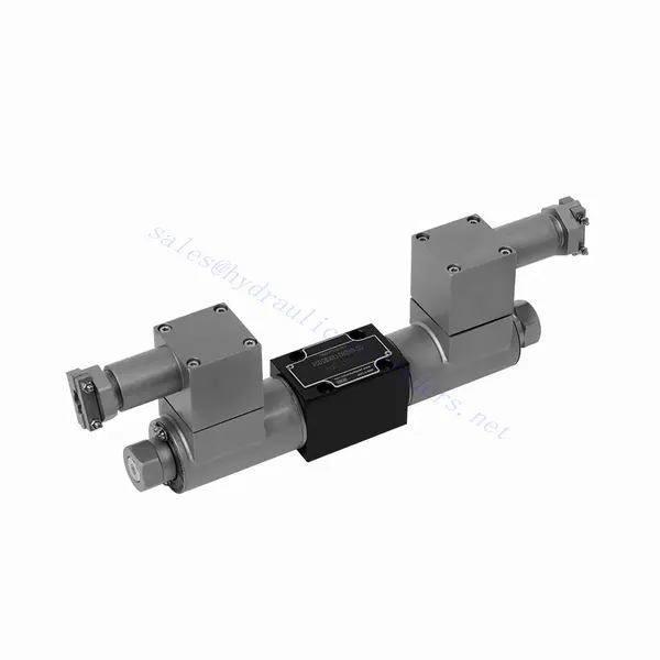
Válvula hidráulica direcional solenóide à prova de explosão da série GWE
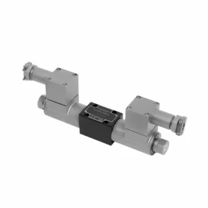

The GWE series explosion-proof solenoid directional hydraulic valve is a cutting-edge product designed to ensure safety and efficiency in hydraulic systems operating in hazardous environments. With its explosion-proof capabilities and reliable performance, this valve offers precise control, enhanced safety features, and optimal fluid flow management.
The GWE series explosion-proof solenoid directional hydraulic valve is a remarkable solution for achieving safety and efficiency in hydraulic systems operating in hazardous environments. With its explosion-proof design, solenoid technology, directional control capabilities, and versatility, this valve provides reliable performance and precise fluid flow management. By following the recommended usage methods and adhering to regular maintenance practices, the GWE series valve ensures safe and efficient operation in explosive atmospheres. Upgrade your hydraulic system with the GWE series explosion-proof solenoid directional hydraulic valve and experience the benefits of enhanced safety and optimized fluid flow control.
GWE Series Explosion-proof Solenoid Directional Hydraulic Valve Key Characteristics:
- Design à prova de explosão:
- The GWE series hydraulic valve is precisely engineered to operate safely in explosive atmospheres, such as those containing flammable gases or dust.
- It complies with stringent safety standards and certifications, ensuring reliable performance and preventing potential ignition sources.
- Solenoid Technology:
- This hydraulic valve utilizes solenoid technology for precise control of fluid flow.
- The electromagnetic coil generates a magnetic field that actuates the valve, enabling quick response times and accurate positioning.
- Controle direcional:
- The GWE series valve provides efficient directional control of hydraulic fluid flow, allowing for the activation and deactivation of specific hydraulic actuators.
- It ensures smooth and reliable operation of various hydraulic functions, such as cylinder extension and retraction or motor direction changes.
- Versatilidade e compatibilidade:
- This hydraulic valve is highly versatile and compatible with various systems and applications.
- It can be integrated into industrial machinery, mobile equipment, and automation systems operating in hazardous environments.
GWE Series Explosion-proof Solenoid Directional Hydraulic Valve Parameter:
| Especificações | NG6 | NG10 | ||
| Posição de instalação | Opcional | Opcional | ||
| Temperatura ambiente | °C | -30 to +50(NBR seal) | ||
| -20 to +50(FKM seal) | ||||
| Peso | Válvula solenóide simples | kg | 2.6 | 5.9 |
| Válvula solenóide dupla | kg | 4.3 | 8.9 | |
| Pressão máxima de trabalho | Port P, A, B | bar | 350 | 315 |
| Porto T | bar | 210 | ||
| When the working pressure exceeds the allowable pressure, the valves with symbols a and B must use T as the oil release port. | ||||
| Taxa de fluxo máxima | L/min | 80 | 120 | |
| Tipo V | milímetros2 | / | 11(A/B → T);10.3(P → A/B) | |
| Flowarea (switching neutral position ) | Tipo Q | milímetros2 | para o símbolo Q 6% de seção transversal nominal | 2,5(A/B → T) |
| Tipo W | milímetros2 | para o símbolo W 3% de seção transversal nominal | 5,5(A/B → T) | |
| Fluido | Óleo mineral adequado para vedação NBR e FKM | |||
| Éster de fosfato para selo FKM | ||||
| Faixa de temperatura do fluido | °C | -30 a +80 (vedação NBR) | ||
| -20 a +80 (selo FKM) | ||||
| Faixa de viscosidade | milímetros2/s | 2,8 a 500 | ||
| Grau de contaminação | Grau máximo permitido de contaminação do fluido: Classe 9. NAS 1638 ou 20/18/15, ISO4406 | |||
GWE Series Explosion-proof Solenoid Directional Hydraulic Valve Advantages:
NG6
• Direct explosion proof solenoid slide valve as standard type
• A face de instalação segue as normas DIN 24340 A, ISO 4401 e CETOP-RP 121H.
• Wet DC explosion proof solenoid
• Explosion proof solenoid can rotate 90°
• Substituir a bobina sem liberar óleo
NG10
• Explosion proof solenoid slide valve as standard typen
• A face de instalação segue as normas DIN 24340 A, ISO 4401 e CETOP-RP 121H.
• Wet DC explosion proof solenoid
• Explosion proof solenoid can rotate 90°
• Substituir a bobina sem liberar óleo
Usage Method Of GWE Series Explosion-proof Solenoid Directional Hydraulic Valve:
- Avaliação de áreas de risco:
- Realizar uma avaliação completa da área classificada como perigosa para identificar os requisitos específicos de proteção contra explosões e a respectiva classificação.
- Determine as medidas de segurança e precauções adequadas necessárias para cumprir as normas.
- Seleção de válvulas:
- Select the GWE Series Valve with the appropriate specifications, considering pressure ratings, flow capacity, and voltage requirements.
- Garantir a compatibilidade com o sistema hidráulico e com o ambiente perigoso específico.
- Instalação:
- Follow the manufacturer’s instructions for properly installing the GWE series valve in the hydraulic system.
- Assegure uma montagem segura e conexões elétricas adequadas, respeitando os valores de torque recomendados e as diretrizes de fiação.
- Controle e ativação:
- Utilize the recommended control method, such as electrical signals or remote activation, to operate the GWE Series Valve.
- Conecte a válvula a uma fonte de alimentação e sistema de controle adequados, seguindo os diagramas de fiação fornecidos.
How Does A Hydraulic Check Valve Work?
A hydraulic check valve, also known as a one-way or non-return valve, is a crucial component in hydraulic systems that allows fluid flow in only one direction while preventing backflow. It ensures the proper operation and safety of hydraulic systems by preventing the reverse flow of fluid, maintaining pressure, and controlling the movement of hydraulic actuators. Here’s an overview of how a hydraulic check valve works:
- Estrutura da válvula:
- A hydraulic check valve typically consists of a valve body, seat, and a movable element such as a ball, disc, or poppet.
- The valve body contains inlet and outlet ports through which the fluid enters and exits the valve.
- The valve seat is a sealing surface where the movable element makes contact to block or allow fluid flow.
- Flow Direction:
- Hydraulic check valves are designed to allow fluid flow in one direction (forward flow) and prevent flow in the opposite direction (reverse flow).
- The valve body is marked with an arrow indicating the direction of permissible flow.
- Forward Flow:
- When fluid pressure in the hydraulic system exceeds a certain threshold, it overcomes the force exerted by the movable element against the valve seat.
- The fluid pushes the movable element away from the valve seat, creating an open pathway for fluid flow through the valve.
- Reverse Flow Prevention:
- In the absence of forward flow or when the pressure on the outlet side of the valve exceeds the inlet side, the movable element is forced against the valve seat.
- The sealing surface of the valve seat prevents fluid from flowing in the reverse direction by creating a tight seal.
- Check Valve Types:
- Ball Check Valve: It consists of a ball that rests on the valve seat. When fluid pressure exceeds the force holding the ball against the seat, the ball lifts, allowing fluid to pass through.
- Swing Check Valve: It has a hinged disc that swings open to allow forward flow and swings closed under reverse flow conditions.
- Poppet Check Valve: It features a spring-loaded poppet that lifts off the valve seat to enable flow in the forward direction and closes to block reverse flow.
- Aplicações:
- Hydraulic check valves are used in various hydraulic systems to prevent backflow, maintain pressure, and control the movement of hydraulic actuators.
- They are commonly found in hydraulic cylinders, pumps, motors, control valves, and other components to ensure proper system operation.
- Benefícios:
- Preventing Backflow: The primary function of a hydraulic check valve is to prevent reverse flow, which can cause system instability, damage, or inefficient operation.
- Pressure Maintenance: Check valves help maintain pressure by preventing pressure loss due to backflow.
- Control and Safety: By allowing flow in one direction only, check valves enable precise control of hydraulic systems and contribute to their safe operation.
Aptidão e capacidade da fábrica:
(1) Montagem
Temos uma plataforma de montagem de pesquisa e desenvolvimento independente de primeira classe. A oficina de produção de cilindros hidráulicos tem quatro linhas de montagem semiautomáticas de cilindros de elevação e uma linha de montagem automática de cilindros de inclinação, com uma capacidade de produção anual projetada de 1 milhão de peças. A oficina de cilindros especiais é equipada com várias especificações de um sistema de montagem de limpeza semiautomática com uma capacidade de produção anual projetada de 200.000 peças e equipada com famosos equipamentos de usinagem CNC, um centro de usinagem, um equipamento especial de processamento de cilindros de alta precisão, uma máquina de solda robotizada, uma máquina de limpeza automática, uma máquina de montagem automática de cilindros e uma linha de produção de pintura automática. O equipamento crítico existente é de mais de 300 conjuntos (conjuntos). A alocação ideal e o uso eficiente dos recursos do equipamento garantem os requisitos de precisão dos produtos e atendem às necessidades de alta qualidade dos produtos.


(2) Usinagem
A oficina de usinagem é equipada com um centro de torneamento de trilho inclinado personalizado, um centro de usinagem, uma máquina de brunimento de alta velocidade, um robô de soldagem e outros equipamentos relacionados, que podem lidar com o processamento de tubos de cilindros com diâmetro interno máximo de 400 mm e comprimento máximo de 6 metros.


(3) Soldagem


(4) Pintura e revestimento
Com linhas de revestimento de tinta à base de água automáticas de cilindros de pequeno e médio porte, para obter carregamento e descarregamento automáticos de robôs e pulverização automática, a capacidade projetada é de 4.000 peças por turno;
Também temos uma linha de produção de tinta semiautomática para cilindros grandes, acionada por uma corrente elétrica, com capacidade de projeto de 60 caixas por turno.


(5) Testes
Temos instalações de inspeção e bancos de teste de primeira classe para garantir que o desempenho do cilindro atenda aos requisitos.


Somos um dos melhores fabricantes de cilindros hidráulicos. Oferecemos cilindros hidráulicos completos. Também fornecemos os correspondentes caixas de câmbio agrícolas. Exportamos nossos produtos para clientes em todo o mundo e conquistamos uma boa reputação devido à qualidade superior de nossos produtos e ao serviço pós-venda. Convidamos clientes nacionais e estrangeiros a entrar em contato conosco para negociar negócios, trocar informações e cooperar conosco!