


Válvula direcional solenóide KSE66-C0820

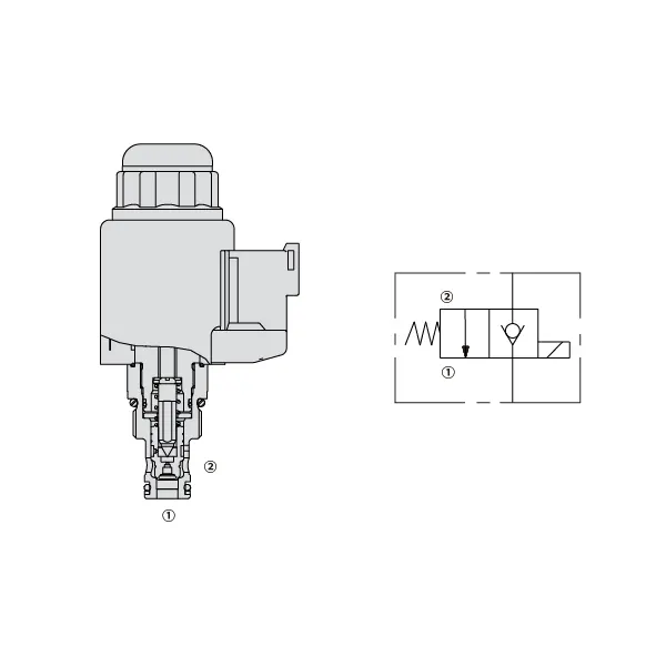
A válvula direcional solenóide KSE66-C0820 é um componente inovador e confiável, projetado para elevar os sistemas de controle de fluidos a um novo patamar. Com seus recursos avançados e capacidades de controle preciso, esta válvula é a solução perfeita para diversas aplicações industriais. Seja na manufatura, automação ou outros processos de controle de fluidos, a válvula direcional solenóide KSE66-C0820 garante operação perfeita e desempenho excepcional.
A válvula direcional solenóide KSE66-C0820 oferece capacidades excepcionais de controle de fluidos, garantindo desempenho ideal em diversas aplicações industriais. Com sua construção de alta qualidade, controle preciso, design compacto e tempo de resposta rápido, esta válvula é uma escolha confiável para otimizar sistemas de controle de fluidos. Seguindo o método de uso correto e implementando práticas regulares de manutenção, você pode maximizar o potencial da válvula direcional solenóide KSE66-C0820 e alcançar eficiência superior no controle de fluidos em suas operações. Atualize seu sistema de controle de fluidos hoje mesmo com a confiabilidade e o desempenho da válvula direcional solenóide KSE66-C0820.
Características da válvula direcional solenóide KSE66-C0820:
- Construção de alta qualidade: A válvula direcional solenóide KSE66-C0820 é fabricada com materiais de alta qualidade, garantindo durabilidade excepcional e desempenho de longa duração. Ela foi projetada para suportar condições operacionais exigentes, incluindo altas pressões e ambientes agressivos, sem comprometer sua funcionalidade.
- Controle preciso de fluidos: Com seu design de vanguarda, a válvula direcional solenóide KSE66-C0820 oferece controle preciso sobre o fluxo e a direção do fluido. Ela permite ajustes precisos, proporcionando desempenho e eficiência ideais em diversas aplicações.
- Compacto e leve: Esta válvula foi projetada para ser compacta e leve, facilitando sua integração em diferentes sistemas de controle de fluidos. Seu design simplificado garante o uso eficiente do espaço, mantendo um excelente desempenho.
- Tempo de resposta rápido: A válvula direcional solenóide KSE66-C0820 possui um tempo de resposta rápido, proporcionando uma comutação rápida e confiável entre diferentes fluxos. Isso garante uma operação suave e melhora o desempenho do sistema, mesmo em aplicações dinâmicas e com restrições de tempo.
Parâmetros da válvula direcional solenóide KSE66-C0820:
| Pressão nominal | 350 bar (5000 psi) |
| Pico de fluxo | 40 L/min (10 gpm) |
| Fluido | Óleo mineral - Adequado para vedações de Buna N ou fluorocarbono |
| Éster de fosfato - Adequado para vedações de fluorocarbono | |
| Faixa de temperatura do fluido ℃ | – 30 to 80(Buna N seals) |
| – 20 to 80(Fluorocarbon seals) | |
| Faixa de viscosidade | 7,4 a 420 mm2/s |
| Grau de contaminação do fluido | O nível mínimo de poluição é o ISO4406 nível 18/16/13, sendo recomendado o nível 15/13/11 para prolongar a vida útil. |
| Vazamento interno | ≦ 5 d/min |
| Cavidade | VC08-2 |
| Peso | 0,33 kg |
| Classificação de serviço da bobina | Contínuo de 85% a 115% de tensão nominal |
| Consumo inicial de corrente da bobina a 20°C | 1,5 A a 12 VCC; 0,8 A a 24 VCC |
| Tensão mínima de entrada | 85% de nominal a 350 bar |
Vantagens da válvula direcional solenóide KSE66-C0820:
• Bobina nominal para serviço contínuo
• Os cartuchos são intercambiáveis em termos de voltagem
• Bobinas elétricas à prova d'água opcionais com classificação até IP69K
• Cavidade comum da indústria
• Peças temperadas para longa vida útil
Método de utilização da válvula direcional solenóide KSE66-C0820:
- Avaliação do Sistema: Avalie os requisitos do sistema de controle de fluidos, incluindo classificações de pressão, vazões e necessidades de controle direcional. Certifique-se de que a válvula direcional solenóide KSE66-C0820 seja compatível com sua aplicação específica.
- Montagem e Conexão: Selecione o método de montagem apropriado com base na configuração do seu sistema e no espaço disponível. Instale a válvula firmemente, alinhando-a com as linhas de fluido. Conecte a válvula usando conexões e acessórios compatíveis, garantindo conexões firmes e sem vazamentos.
- Conexão elétrica: Connect the solenoid of the valve to the appropriate power supply following the manufacturer’s guidelines. Ensure correct wiring and observe safety precautions during the electrical connection process.
- Testes e Calibração: Gradually introduce fluid flow into the system and monitor the valve’s performance. Test different operating conditions, such as pressure and flow variations, and calibrate the valve settings as needed to achieve optimal control and system functionality.
Como substituir o cartucho da válvula da torneira Delta?
Para substituir o cartucho da válvula em uma torneira Delta, siga estas instruções passo a passo:
- Reúna as ferramentas necessárias: Você precisará de um conjunto de chaves Allen, um alicate (ajustável ou de junta universal), uma chave de fenda (Phillips ou de fenda reta) e um cartucho de válvula Delta de reposição específico para o modelo da sua torneira.
- Feche o registro de água: Localize as válvulas de fechamento sob a pia ou no cano principal de abastecimento de água e feche o registro da torneira. Abra os registros da torneira para liberar qualquer água restante nos canos e certifique-se de que a água esteja completamente desligada.
- Desmonte a alavanca da torneira: As torneiras Delta possuem diferentes estilos de alavanca, como alavanca única ou alavanca dupla. Para uma alavanca única, localize o parafuso de fixação na alavanca, geralmente localizado sob uma tampa ou botão decorativo. Use uma chave Allen para remover o parafuso de fixação e puxe a alavanca. Para uma torneira com alavanca dupla, remova a alavanca desaparafusando a tampa decorativa ou o parafuso da alavanca.
- Remova o cartucho: Após remover a alavanca, você verá o cartucho. Use um alicate para soltar e remover a porca do cartucho, girando-a no sentido anti-horário. Se estiver difícil de soltar, você pode usar uma ferramenta de remoção de cartucho para obter mais alavancagem. Puxe o cartucho para fora do corpo da torneira.
- Instale o cartucho de substituição: Pegue o novo cartucho da válvula Delta e alinhe-o com o corpo da torneira, certificando-se de que todas as abas ou encaixes coincidam corretamente. Empurre o cartucho suavemente para dentro do corpo da torneira até que ele se encaixe firmemente.
- Remonte a torneira: Após instalar o novo cartucho, monte a torneira na ordem inversa. Deslize a porca do cartucho de volta para o corpo da válvula e aperte-a com um alicate. Certifique-se de que esteja bem apertada, mas evite apertá-la demais. Recoloque o manípulo da torneira e aperte o parafuso de fixação ou o parafuso do manípulo.
- Abra o abastecimento de água: Abra lentamente o abastecimento de água usando as válvulas de corte ou a entrada principal de água. Verifique se há vazamentos ao redor da torneira e do registro. Se houver vazamentos, aperte a porca do cartucho ou o registro conforme necessário.
- Teste a torneira: Com o abastecimento de água restabelecido, teste a torneira abrindo os registros e verificando se o funcionamento está normal. Certifique-se de que a água quente e fria fluam corretamente e ajuste a temperatura conforme desejado.
Aptidão e capacidade da fábrica:
(1) Montagem
Temos uma plataforma de montagem de pesquisa e desenvolvimento independente de primeira classe. A oficina de produção de cilindros hidráulicos tem quatro linhas de montagem semiautomáticas de cilindros de elevação e uma linha de montagem automática de cilindros de inclinação, com uma capacidade de produção anual projetada de 1 milhão de peças. A oficina de cilindros especiais é equipada com várias especificações de um sistema de montagem de limpeza semiautomática com uma capacidade de produção anual projetada de 200.000 peças e equipada com famosos equipamentos de usinagem CNC, um centro de usinagem, um equipamento especial de processamento de cilindros de alta precisão, uma máquina de solda robotizada, uma máquina de limpeza automática, uma máquina de montagem automática de cilindros e uma linha de produção de pintura automática. O equipamento crítico existente é de mais de 300 conjuntos (conjuntos). A alocação ideal e o uso eficiente dos recursos do equipamento garantem os requisitos de precisão dos produtos e atendem às necessidades de alta qualidade dos produtos.


(2) Usinagem
A oficina de usinagem é equipada com um centro de torneamento de trilho inclinado personalizado, um centro de usinagem, uma máquina de brunimento de alta velocidade, um robô de soldagem e outros equipamentos relacionados, que podem lidar com o processamento de tubos de cilindros com diâmetro interno máximo de 400 mm e comprimento máximo de 6 metros.


(3) Soldagem


(4) Pintura e revestimento
Com linhas de revestimento de tinta à base de água automáticas de cilindros de pequeno e médio porte, para obter carregamento e descarregamento automáticos de robôs e pulverização automática, a capacidade projetada é de 4.000 peças por turno;
Também temos uma linha de produção de tinta semiautomática para cilindros grandes, acionada por uma corrente elétrica, com capacidade de projeto de 60 caixas por turno.


(5) Testes
Temos instalações de inspeção e bancos de teste de primeira classe para garantir que o desempenho do cilindro atenda aos requisitos.


Somos um dos melhores fabricantes de cilindros hidráulicos. Oferecemos cilindros hidráulicos completos. Também fornecemos os correspondentes caixas de câmbio agrícolas. Exportamos nossos produtos para clientes em todo o mundo e conquistamos uma boa reputação devido à qualidade superior de nossos produtos e ao serviço pós-venda. Convidamos clientes nacionais e estrangeiros a entrar em contato conosco para negociar negócios, trocar informações e cooperar conosco!