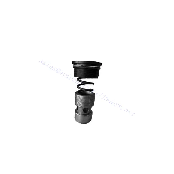
M-SR Series Check Hydraulic Valve Cartridge
Como um dos fabricantes, fornecedores e exportadores de produtos mecânicos de cilindros hidráulicos, oferecemos cilindros hidráulicos e muitos outros produtos.
Entre em contato conosco para obter detalhes.
Correio eletrônico:sales@hydraulic-cylinders.net
Fabricante, fornecedor e exportador de cilindros hidráulicos.
M-SR Series Check Hydraulic Valve Cartridge
The M-SR series check hydraulic valve cartridge is versatile and essential in hydraulic systems. This valve cartridge is designed to regulate fluid flow and prevent backflow and offers reliable performance, durability, and ease of installation.
The M-SR series check hydraulic valve cartridge is a reliable and efficient solution for fluid control in hydraulic systems. With efficient check valve functionality, compact design, high flow capacity, and robust construction, this valve cartridge ensures optimal system performance, prevents backflow, and enhances overall efficiency. By following the recommended usage methods and maintenance practices, the M-SR series check hydraulic valve cartridge delivers reliable operation and extends the lifespan of hydraulic systems. Upgrade your hydraulic system with the m-sr series check hydraulic valve cartridge and experience efficient and reliable fluid control.
M-SR Series Check Hydraulic Valve Cartridge Key Characteristics:
- Efficient Check Valve Functionality:
- The M-SR series valve cartridge features a built-in check valve mechanism that enables the unidirectional flow of hydraulic fluid.
- It effectively prevents backflow and ensures fluid flows in the desired direction, minimizing the risk of system damage and inefficiency.
- Compact and Versatile Design:
- The valve cartridge is compact, making it suitable for applications with limited space or where weight considerations are crucial.
- Its versatile design allows easy integration into various hydraulic systems, including mobile machinery, industrial equipment, and hydraulic power units.
- Alta capacidade de fluxo:
- Despite its compact size, the M-SR series valve cartridge offers high flow capacity, allowing for efficient fluid transfer and system performance.
- It minimizes pressure drops, ensuring optimal hydraulic power delivery to actuators and other components.
- Construção robusta:
- Constructed from high-quality materials, the M-SR series valve cartridge demonstrates excellent durability and resistance to wear and corrosion.
- It is designed to withstand demanding operating conditions, prolonging the valve cartridge’s lifespan and reducing maintenance requirements.
M-SR Series Check Hydraulic Valve Cartridge Parameter:
| Especificações | bar | NG6-30 | |||||
| Pressão máxima de operação | bar | 315 | |||||
| pressão de rachadura | bar | Consulte a curva característica. | |||||
| Taxa de fluxo máxima | L/min | Consulte a curva característica. | |||||
| Faixa de viscosidade | milímetros2/s | 2,8 a 380 | |||||
| Faixa de temperatura do fluido | °C | -30 to +80(NBR seals) | |||||
| -20 a +80 (selos FKM) | |||||||
| Fluido | Óleo mineral adequado para vedação NBR e FKM | ||||||
| Éster de fosfato para selo FKM | |||||||
| Grau de contaminação | Grau máximo permitido de contaminação do fluido: Classe 9. NAS 1638 ou 20/18/15, ISO4406 | ||||||
| Tamanho | 8 | 10 | 15 | 20 | 25 | 30 | |
| Weight: Right angled check valve cartridge | kg | 0.03 | 0.05 | 0.08 | 0.14 | 0.32 | 0.47 |
M-SR Series Check Hydraulic Valve Cartridge Advantages:
NG6-30
• Usado na instalação de blocos de caminho de óleo
• Leak-free closure
• Various opening pressures available (see model description)
Usage Method Of M-SR Series Check Hydraulic Valve Cartridge:
- Análise de Sistemas:
- Before installation, thoroughly analyze the hydraulic system to determine the specific requirements and operational parameters.
- Consider factors such as flow rates, pressure ratings, and compatibility with the M-SR series valve cartridge.
- Seleção de válvulas:
- Select the appropriate M-SR series valve cartridge variant based on the system requirements and specifications.
- Consider factors like flow capacity, pressure ratings, and compatibility with other system components.
- Instalação:
- Follow the manufacturer’s instructions for properly installing the M-SR series valve cartridge in the hydraulic system.
- Ensure a secure fit within the valve cavity, proper alignment with the fluid flow path, and appropriate sealing to prevent leaks.
- Direção do fluxo de fluido:
- Ensure the M-SR Series Valve Cartridge is installed in the correct orientation, allowing for the desired fluid flow direction.
- Align the valve cartridge with the system’s flow path, ensuring proper engagement of the check valve mechanism.
How Does A Hydraulic Diverter Valve Work?
A hydraulic diverter valve is a key component in hydraulic systems that allows the operator to redirect hydraulic fluid flow from one path to another. It provides flexibility in controlling the flow direction and enables the use of multiple hydraulic actuators with a single hydraulic power source. Here’s a breakdown of how a hydraulic diverter valve works:
- Estrutura da válvula:
- A hydraulic diverter valve typically consists of a valve body with multiple ports, a movable spool or ball, and actuators such as levers, solenoids, or pilot pressure mechanisms.
- The valve body contains internal passages and chambers that direct the flow of hydraulic fluid.
- Fluid Flow Paths:
- The diverter valve has multiple ports that connect to different hydraulic components in the system, such as the pump, reservoir, actuators, and other valves.
- These ports include an inlet port, outlet ports, and work ports, each serving a specific purpose in controlling the fluid flow.
- Spool or Ball:
- The valve body houses a movable spool or ball that controls the flow of hydraulic fluid.
- The spool can slide within the valve body, while the ball can rotate or move linearly to open or close specific passages.
- Actuation Mechanisms:
- Hydraulic diverter valves can be actuated manually, electrically, or hydraulically, depending on the specific design and application requirement.
- Manual actuation involves levers or handles that the operator physically moves to position the spool or ball.
- Electrical actuation utilizes solenoids that receive electrical signals to shift the spool or ball, allowing for remote control and automation.
- Hydraulic actuation employs pilot pressure to move the spool or ball, often in conjunction with electrical or manual control.
- Posições das válvulas:
- Depending on the valve design, there are typically multiple positions that the spool or ball can assume, each corresponding to a specific flow path.
- Common positions include neutral, where all ports are blocked, and various actuating positions that allow flow between specific ports.
- As the spool or ball shifts, it aligns with specific ports, opening or closing passages and directing the hydraulic fluid accordingly.
- Operator Input:
- The operator engages the hydraulic diverter valve by actuating the manual lever, applying electrical signals to solenoids, or manipulating pilot pressure.
- This input determines the desired valve position, which in turn determines the flow direction and the action of the hydraulic actuators.
- Operação do sistema:
- Once the hydraulic diverter valve is in the desired position, hydraulic fluid flows through the appropriate passages and ports.
- This flow of fluid can be directed to different hydraulic actuators, allowing for selective control of the actuator’s movement or operation.
Aptidão e capacidade da fábrica:
(1) Montagem
Temos uma plataforma de montagem de pesquisa e desenvolvimento independente de primeira classe. A oficina de produção de cilindros hidráulicos tem quatro linhas de montagem semiautomáticas de cilindros de elevação e uma linha de montagem automática de cilindros de inclinação, com uma capacidade de produção anual projetada de 1 milhão de peças. A oficina de cilindros especiais é equipada com várias especificações de um sistema de montagem de limpeza semiautomática com uma capacidade de produção anual projetada de 200.000 peças e equipada com famosos equipamentos de usinagem CNC, um centro de usinagem, um equipamento especial de processamento de cilindros de alta precisão, uma máquina de solda robotizada, uma máquina de limpeza automática, uma máquina de montagem automática de cilindros e uma linha de produção de pintura automática. O equipamento crítico existente é de mais de 300 conjuntos (conjuntos). A alocação ideal e o uso eficiente dos recursos do equipamento garantem os requisitos de precisão dos produtos e atendem às necessidades de alta qualidade dos produtos.


(2) Usinagem
A oficina de usinagem é equipada com um centro de torneamento de trilho inclinado personalizado, um centro de usinagem, uma máquina de brunimento de alta velocidade, um robô de soldagem e outros equipamentos relacionados, que podem lidar com o processamento de tubos de cilindros com diâmetro interno máximo de 400 mm e comprimento máximo de 6 metros.

(3) Soldagem

(4) Pintura e revestimento
Com linhas de revestimento de tinta à base de água automáticas de cilindros de pequeno e médio porte, para obter carregamento e descarregamento automáticos de robôs e pulverização automática, a capacidade projetada é de 4.000 peças por turno;
Também temos uma linha de produção de tinta semiautomática para cilindros grandes, acionada por uma corrente elétrica, com capacidade de projeto de 60 caixas por turno.


(5) Testes
Temos instalações de inspeção e bancos de teste de primeira classe para garantir que o desempenho do cilindro atenda aos requisitos.

Somos um dos melhores fabricantes de cilindros hidráulicos. Oferecemos cilindros hidráulicos completos. Também fornecemos os correspondentes caixas de câmbio agrícolas. Exportamos nossos produtos para clientes em todo o mundo e conquistamos uma boa reputação devido à qualidade superior de nossos produtos e ao serviço pós-venda. Convidamos clientes nacionais e estrangeiros a entrar em contato conosco para negociar negócios, trocar informações e cooperar conosco!
Cilindro hidráulico Aplicação:
