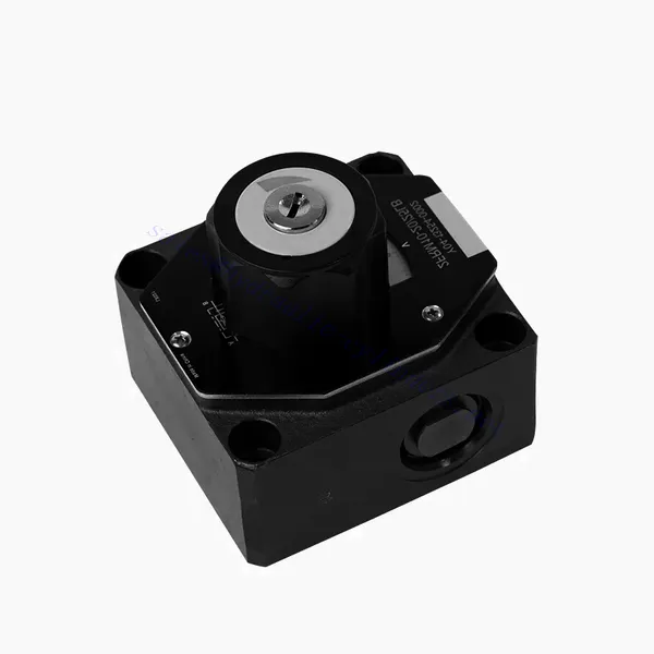
Valvă hidraulică de control al debitului din seria FRM
Valvă hidraulică de control al debitului din seria FRM
Supapa hidraulică de control al debitului din seria FRM este o componentă hidraulică de ultimă generație, concepută pentru a îmbunătăți performanța și controlul sistemelor hidraulice. Cu caracteristicile sale avansate și funcționalitatea fiabilă, această supapă oferă un control precis al debitului și o eficiență optimă.
Supapa hidraulică de control al debitului din seria FRM este o soluție fiabilă și versatilă pentru optimizarea controlului debitului în sistemele hidraulice. Datorită capacităților sale precise de control al debitului, stabilității presiunii și temperaturii și construcției durabile, această supapă oferă performanțe și eficiență îmbunătățite. Urmând metodele de utilizare recomandate și instrucțiunile de întreținere, operatorii pot maximiza beneficiile supapei hidraulice de control al debitului din seria FRM, asigurând o funcționare lină și un control fiabil al debitului în aplicațiile lor hidraulice. Modernizați-vă sistemul hidraulic cu această supapă avansată și experimentați precizie, eficiență și productivitate ca niciodată.
Caracteristici cheie ale supapei hidraulice de control al debitului din seria FRM:
- Precizia controlului debitului:
- Valva din seria FRM permite un control precis asupra debitului fluidelor hidraulice, permițând operatorilor să regleze fin și să modifice viteza actuatoarelor.
- Cu precizia sa excepțională, această supapă asigură un control constant al debitului, rezultând o performanță îmbunătățită a sistemului și o productivitate sporită.
- Aplicație versatilă:
- Valva din seria FRM este extrem de versatilă și compatibilă cu diverse sisteme hidraulice, inclusiv utilaje industriale, echipamente de construcții și aplicații mobile.
- Adaptabilitatea sa îl face o alegere ideală pentru o gamă largă de configurații hidraulice, oferind un control fiabil și eficient al debitului.
- Stabilitate la presiune și temperatură:
- Această supapă hidraulică este proiectată pentru a menține un control constant al debitului chiar și în condiții variabile de presiune și temperatură.
- Asigură o performanță stabilă și previne fluctuațiile de debit, protejând integritatea și fiabilitatea sistemului hidraulic.
- Construcție durabilă:
- Valva din seria FRM este construită din materiale de înaltă calitate, asigurând durabilitate și fiabilitate pe termen lung în medii de operare solicitante.
- Designul său robust îi permite să reziste la presiuni ridicate, vibrații și temperaturi extreme, oferind o soluție fiabilă pentru aplicații hidraulice.
Parametrul supapei hidraulice de control al debitului din seria FRM:
NG6
| Supapă de control al debitului | |||||||||||
| Presiune maximă de funcționare - Portul A | bar | 315 | |||||||||
| Diferența de presiune ΔP pentru retur liber de la B la A | Vezi curbele caracteristice | ||||||||||
| Diferența minimă de presiune | bar | 6 până la 14 | |||||||||
| Stabilitate la presiune până la P= 315 bar | % | ±2(Qmax) | |||||||||
| Flux | Qmax | L/min | 0.2 | 0.6 | 1.5 | 3 | 6 | 10 | 16 | 25 | 32 |
| Qmin până la 100 bar | mL/min | 15 | 15 | 15 | 15 | 25 | 50 | 70 | 100 | 250 | |
| Qmin până la 315 bar | 25 | 25 | 25 | 25 | 25 | 50 | 70 | 100 | 250 | ||
| Fluid | Ulei mineral, ester fosfat | ||||||||||
| Interval de temperatură al fluidului | ℃ | – 20 până la + 80 | |||||||||
| Interval de vâscozitate | mm²/s | 10 până la 800 | |||||||||
| Gradul de contaminare | Grad maxim admis de contaminare a fluidului: Clasa 9. NAS 1638 sau 20/18/15, ISO4406 | ||||||||||
| Poziția de instalare | Opțional | ||||||||||
| Interval de temperatură în circumstanțe | ℃ | -20 până la +50 | |||||||||
| Greutate | 2FRM6A…2FRM6B… | kg | aproximativ 1,3 | ||||||||
| 2FRM6SB… | kg | aproximativ 1,5 | |||||||||
| Redresor | |||||||||||
| Debit nominal | bar | 320 | |||||||||
| Presiune maximă de funcționare | bar | până la 210 | |||||||||
| Presiunea fisurii | bar | 0.7 | |||||||||
| Greutate | kg | aproximativ 0,9 | |||||||||
NG5/10/16
| Supapă de control al debitului | ||||||||||||||||
| Presiune maximă de funcționare - Portul A | bar | 315 | ||||||||||||||
| Diferența de presiune ΔP pentru retur liber de la B la A | Vezi curbele caracteristice | |||||||||||||||
| Diferența minimă de presiune | bar | 6 până la 14 | ||||||||||||||
| Fluid | Ulei mineral, ester fosfat | |||||||||||||||
| Interval de temperatură al fluidului | ℃ | – 20 până la + 80 | ||||||||||||||
| Interval de vâscozitate | mm²/s | 10 până la 800 | ||||||||||||||
| Gradul de contaminare | Grad maxim admis de contaminare a fluidului: Clasa 9. NAS 1638 sau 20/18/15, ISO4406 | |||||||||||||||
| Dimensiune | mm | 5 | 10 | 16 | ||||||||||||
| Debit maxim | L/min | 0.2 | 0.6 | 1.2 | 3 | 6 | 10 | 15 | 10 | 16 | 25 | 50 | 60 | 100 | 160 | |
| Returnarea uleiului de la B la A | mL/min | 0.5 | 0.5 | 0.6 | 0.9 | 1.8 | 3.6 | 6.7 | 2 | 2.5 | 3.5 | 6 | 2.8 | 4.3 | 7.3 | |
| interval de stabilitate a fluxului (%Qmax) (-20-±80℃) | ±5 | ±3 | ±2 | ±2 | ||||||||||||
| ±2 (P=210 bar) | ±2 (P=350 bar) | |||||||||||||||
| Presiunea de lucru | bar | 210 | 350 | |||||||||||||
| Reducerea presiunii minime | bar | 3-5 | 6-8 | 3-7 | 5-12 | |||||||||||
| Greutate | kg | 1.6 | 3.4 | 7.4 | ||||||||||||
| Redresor | ||||||||||||||||
| Fluid | Ulei mineral, ester fosfat | |||||||||||||||
| Interval de temperatură al fluidului | -20 până la +80 | |||||||||||||||
| Interval de vâscozitate | 10 până la 800 | |||||||||||||||
| Gradul de contaminare | Grad maxim admis de contaminare a fluidului: Clasa 9. NAS 1638 sau 20/18/15, ISO4406 | |||||||||||||||
| Dimensiune | 5 | 10 | 16 | |||||||||||||
| Flux | 15 | 50 | 160 | |||||||||||||
| Presiunea de lucru | 210 | 315 | 315 | |||||||||||||
| Presiunea fisurii | 1 | 1.5 | 1.5 | |||||||||||||
| Greutate | 0.6 | 3.2 | 9.3 | |||||||||||||
Avantajele supapelor hidraulice de control al debitului din seria FRM:
• Montare subplacă de bază, vezi catalogul de produse
• Limitator de deplasare pentru compensarea presiunii, opțional
• Supapă unidirecțională opțională
• Buton cu scală, blocare opțională
Metoda de utilizare a supapei hidraulice de control al debitului din seria FRM:
- Evaluarea sistemului:
- Începeți prin evaluarea cerințelor sistemului hidraulic, inclusiv debitele, intervalele de presiune și parametrii de control al debitului doriți.
- Determinați dacă vana din seria FRM este potrivită pentru aplicația specifică, pe baza capacităților sale de control al debitului.
- Selectarea supapelor:
- Selectați varianta corespunzătoare a valvei din seria FRM pe baza parametrilor sistemului, a debitului dorit și a compatibilității cu alte componente ale sistemului.
- Luați în considerare factori precum debitul maxim, presiunea nominală și condițiile de funcționare.
- Instalare:
- Urmați cu atenție instrucțiunile de instalare ale producătorului, asigurându-vă că aliniați corect și că aveți conexiuni sigure ale valvei.
- Acordați atenție indicatoarelor direcției de curgere, asigurându-vă poziționarea corectă a supapei în sistemul hidraulic.
- Reglarea controlului debitului:
- După instalare, reglați setările de control al debitului valvei în funcție de debitul dorit și de cerințele sistemului.
- Reglați fin supapa pentru a obține viteza și performanța dorite ale actuatoarelor hidraulice, optimizând funcționarea generală a sistemului.
Cum funcționează valvele hidraulice?
Supapele hidraulice sunt cruciale în controlul fluxului și direcției fluidului hidraulic într-un sistem hidraulic. Acestea sunt componente esențiale care permit funcționarea precisă a diferitelor mașini și echipamente hidraulice. Iată o explicație simplificată a modului în care funcționează supapele hidraulice:
- Noțiuni de bază ale sistemelor hidraulice:
Sistemele hidraulice utilizează fluide, de obicei ulei, pentru a transmite puterea și a controla mișcarea componentelor mecanice. Aceste sisteme constau dintr-o pompă hidraulică care presurizează lichidul, o serie de supape care controlează curgerea și direcția fluidului și actuatoare hidraulice (cum ar fi cilindri sau motoare) care transformă energia fluidului în forță mecanică sau mișcare. - Tipuri de valve:
Există diverse valve hidraulice, inclusiv valve de control direcțional, valve de control al presiunii, valve de control al debitului și valve de sens invers. Fiecare tip de valvă servește unui scop specific în reglarea debitului, presiunii sau direcției fluidului. - Supape de control direcțional:
Supapele de control direcțional determină calea prin care curge fluidul hidraulic. Acestea au mai multe poziții (cum ar fi deschis, închis sau parțial deschis) și mai multe orificii pentru a direcționa fluidul către diferite secțiuni ale sistemului hidraulic. - Componente ale supapei:
Supapele hidraulice constau de obicei dintr-un corp de supapă, care conține pasaje și canale interne, și un element mobil de supapă sau o bobină care glisează în interiorul corpului supapei. Bobina are diferite zone sau orificii care se aliniază cu pasajele interne pentru a controla curgerea fluidului. - Mișcarea bobinei:
Poziția bobinei în corpul valvei determină traiectoria curgerii și, în consecință, direcția curgerii fluidului. Bobina poate fi acționată prin diverse mijloace, cum ar fi legături mecanice, solenoizi sau presiune pilot. - Supape de control al presiunii:
Supapele de control al presiunii reglează presiunea fluidului hidraulic din sistem. Acestea pot menține un anumit nivel de presiune permițând fluidului în exces să se întoarcă în rezervor sau blocând debitul până când se atinge presiunea dorită. - Supape de control al debitului:
Supapele de control al debitului gestionează debitul fluidului în sistemul hidraulic. Acestea pot fi utilizate pentru a controla viteza actuatoarelor hidraulice sau pentru a limita debitul la anumite secțiuni ale sistemului. - Supape de sens invers:
Supapele de sens unic permit curgerea fluidului într-o singură direcție și previn refluxul. Acestea asigură mișcarea fluidului în direcția dorită și evită orice scăderi de presiune nedorite sau pierderi de forță hidraulică. - Acționarea supapei:
Supapele hidraulice pot fi acționate manual, mecanic sau controlate electronic. Pârghiile sau butoanele acționează direct supapele manuale, în timp ce actuatoarele mecanice și electronice permit controlul automat al pozițiilor supapelor în funcție de cerințele sistemului. - Controlul sistemului:
Prin combinarea diferitelor tipuri de supape hidraulice și controlul pozițiilor sau acționării acestora, funcția generală a sistemului hidraulic poate fi reglată cu precizie. Acest lucru permite operatorilor să controleze mișcarea, viteza, forța și direcția actuatoarelor hidraulice, permițând funcționarea precisă și eficientă a mașinilor hidraulice.
Capabilitatea și capacitatea fabricii:
(1) Montaj
Avem o platformă de asamblare independentă de cercetare și dezvoltare de primă clasă. Atelierul de producție a cilindrilor hidraulici are patru linii de asamblare semiautomate pentru cilindri de ridicare și o linie de asamblare automată a cilindrilor de înclinare, cu o capacitate de producție anuală proiectată de 1 milion de bucăți. Atelierul de cilindri speciali este echipat cu diverse specificații ale unui sistem de asamblare semi-automat de curățare, cu o capacitate de producție anuală proiectată de 200.000 și dotat cu echipamente celebre de prelucrare CNC, un centru de prelucrare, un echipament special de prelucrare a cilindrilor de înaltă precizie, o mașină de sudură robotizată, o mașină de curățare automată, o mașină de asamblare automată a cilindrilor și o linie de producție automată de vopsire. Echipamente critice existente de peste 300 de seturi (seturi). Alocarea optimă și utilizarea eficientă a resurselor de echipamente asigură cerințele de precizie ale produselor și satisface nevoile de înaltă calitate ale produselor.


(2) Prelucrare
Atelierul de prelucrare este echipat cu un centru de strunjire cu șină înclinată personalizat, un centru de prelucrare, o mașină de honuire de mare viteză, un robot de sudură și alte echipamente conexe, care pot gestiona prelucrarea tuburilor cilindrice cu un diametru interior maxim de 400 mm și o lungime maximă de 6 metri.

(3) Sudură

(4) Vopsire și acoperire
Cu linii automate de acoperire cu vopsea pe bază de apă cu cilindru de dimensiuni mici și medii, pentru a realiza încărcarea și descărcarea automată a robotului și pulverizarea automată, capacitatea de proiectare de 4000 de bucăți pe schimb;
Avem, de asemenea, o linie de producție semi-automată de vopsire pentru cilindri mari, acționată de un lanț de putere, cu o capacitate de proiectare de 60 de cutii pe schimb.


(5) Testarea
Dispunem de instalații de inspecție și bancuri de testare de primă clasă pentru a ne asigura că performanța cilindrului îndeplinește cerințele.

Suntem unul dintre cei mai buni producători de cilindri hidraulici. Putem oferi o gamă completă de cilindri hidraulici. De asemenea, oferim... cutii de viteze agricoleNe-am exportat produsele către clienți din întreaga lume și ne-am câștigat o bună reputație datorită calității superioare a produselor noastre și a serviciilor post-vânzare. Îi invităm pe clienții din țară și din străinătate să ne contacteze pentru a negocia afaceri, a face schimb de informații și... să coopereze cu noi!


