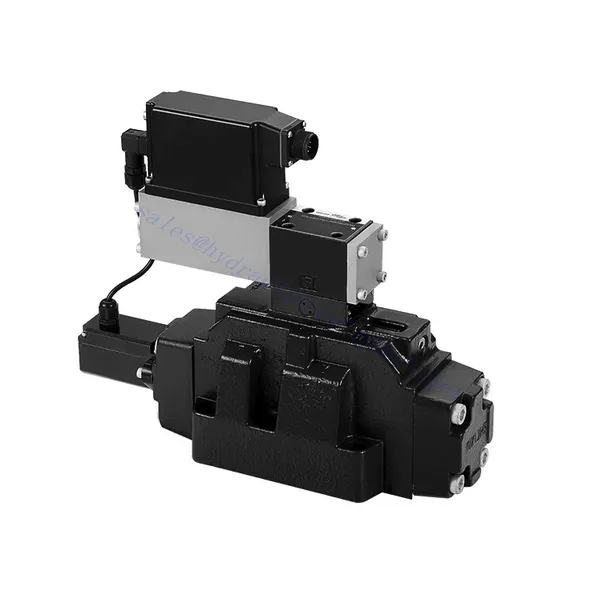
4WRLE Series Pilot Operated Proportional Directional Hydraulic Valve
4WRLE Series Pilot Operated Proportional Directional Hydraulic Valve
The 4WRLE series pilot-operated proportional directional hydraulic valve is a cutting-edge hydraulic component that revolutionizes fluid control in hydraulic systems. This valve combines pilot-operated technology with proportional directional control, offering precise flow regulation and exceptional efficiency.
The 4WRLE series pilot-operated proportional directional hydraulic valve elevates hydraulic control to new heights of precision and efficiency. With its pilot-operated technology and proportional directional control, this valve ensures accurate flow regulation, optimized energy consumption, and enhanced system performance. By following the recommended usage methods and maintenance guidelines, you can unleash the full potential of the 4WRLE series valve and achieve superior hydraulic control. Upgrade your hydraulic system today and experience the power of precision with the 4WRLE series pilot-operated proportional directional hydraulic valve.
4WRLE Series Pilot Operated Proportional Directional Hydraulic Valve Key Characteristics:
- Pilot Operated Technology:
- The 4WRLE series valve incorporates pilot-operated technology, allowing precise fluid flow control and pressure regulation.
- This technology enables efficient energy usage and reduces heat generation, resulting in improved overall system performance and reduced operating costs.
- Proportional Directional Control:
- With its proportional directional control capability, this valve provides accurate and balanced flow adjustment based on control signals.
- The proportional control allows for smooth and precise control of hydraulic actuators, enhancing system performance and minimizing wear and tear.
- Funcționalitate versatilă:
- The 4WRLE series valve offers versatile control over fluid direction, making it suitable for a wide range of hydraulic applications.
- Whether it’s controlling cylinders, motors, or other hydraulic components, this valve ensures seamless activation and deactivation in different directions, enhancing system flexibility and adaptability.
- Capacitate de debit mare:
- Designed to handle high flow rates, the 4WRLE series valve delivers exceptional performance even in demanding applications.
- Its robust construction and optimized flow channels ensure reliable operation and consistent flow control, meeting the requirements of high-power hydraulic systems.
4WRLE Series Pilot Operated Proportional Directional Hydraulic Valve Parameter:
NG6
| General | |||||||
| Proiecta | Spool valve, direct operated, with steel sleeve | ||||||
| Actuation | Proportional solenoid with position control, OBE | ||||||
| Connection type | Subplate mounting, porting pattern according to ISO 4401-03-02-0-05 | ||||||
| Poziția de instalare | Any | ||||||
| Ambient temperature range | ℃ | -20…+50 | |||||
| Greutate | Kg | about 2.75 | |||||
| Maximum vibration resistance (test condition) | Max. 25 g, space vibration test in all directions (24h) | ||||||
| Hidraulic (measured at p=100bar, with HLP46 at ϑoil = 40℃ ±5℃) | |||||||
| Pressure fluid | Mineral oil (HL, HLP)to DIN 51 524 | ||||||
| Interval de vâscozitate | recommended | mm²/s | 20…100 | ||||
| max. permitted | mm²/s | 10…800 | |||||
| Pressure fluid temperature range | ℃ | -20 to +70 | |||||
| Maximum permitted degree of contamination of pressure fluid Purity class to ISO 4406 (c) | Class 18/16/13 | ||||||
| Rated flow (Δp = 35 bar per edge) | L/min | 2 | 4 | 12 | 24 | 40 | |
| Presiune maximă de funcționare | bar | Port A、B、P:315 | |||||
| Max. pressure | bar | Port T: 250 | |||||
| Leakage flow at 100 bar | Linear | cm³/min | <150 | <180 | <300 | <500 | <900; |
| Nonlinear | cm³/min | / | / | / | <300 | <450; | |
| Static/Dynamic | |||||||
| Histerezis | % | ≤0.2 | |||||
| Actuating time for signal step 0 … 100% | Domnișoară | 10 | |||||
| Temperature drift | Zero shift < 1% at ΔT=40℃ | ||||||
| Zero compensation | Ex factory ±1% | ||||||
| Electric, control electronics integrated in the valve | |||||||
| Relative duty cycle | % | 100ED | |||||
| Degree of protection | IP65 | ||||||
| Connection | Plug-in connector 6P+PE, DIN 43563 | ||||||
| Supply voltage Terminal A Terminal B |
24VDCnom | ||||||
| min. 21VDC / max. 40VDC | |||||||
| 0V (ripple max. 2) | |||||||
| Fuse protection, external | AF | 2.5 | |||||
| nput, version “A1” Terminal D (UE) Terminal E |
Differential amplifier, Ri = 100 kΩ | ||||||
| 0…±10V | |||||||
| 0V | |||||||
| Input, version “F1” Terminal D (ID-E) Terminal E (ID-E) |
Load, Rsh = 200 Ω | ||||||
| 4…12…20mA | |||||||
| Current loop ID-E return | |||||||
| Test signal, version “A1” Terminal F (UTest) Terminal C |
LVDT | ||||||
| 0…±10V | |||||||
| Reference 0 V | |||||||
| Test signal, version “F1” Terminal F ( I F-C ) Terminal C ( I F-C ) |
LVDT signal 4 … (12) … 20 mA on external load 200 … 500 Ωmaximum | ||||||
| 4 … (12) … 20mA (output) | |||||||
| Current loop IF-C return | |||||||
| Adjustment | Calibrated before delivery, see characteristic curves | ||||||
NG10
| General | |||||
| Proiecta | Spool valve, directly operated, with steel sleeve | ||||
| Actuation | Proportional solenoid with position control, OBE | ||||
| Connection type | Plate port, porting pattern (ISO 4401-05-04-0-05) | ||||
| Poziția de instalare | Any | ||||
| Interval de temperatură în circumstanțe | ℃ | -20…+50 | |||
| Greutate | Kg | about 7.1 | |||
| Maximum vibration resistance (test condition) | Max. 25 g, space vibration test in all directions (24h) | ||||
| Hydraulic (measured with HLP 46, ϑoil =40℃ ±5℃) | |||||
| Pressure fluid | Hydraulic oil according to DIN 51524…535 | ||||
| Interval de vâscozitate | recommended | mm²/s | 20…100 | ||
| Max. permitted | mm²/s | 10…800 | |||
| Pressure fluid temperature range | ℃ | -20 to +70 | |||
| Max. admissible degree of contamination of the hydraulic fluid,cleanliness class according to ISO 4406 (c) | Class 18/16/13 | ||||
| Rated flow(Δp = 35 bar per edge) | L/min | 50 | 100 | ||
| Presiune maximă de funcționare | bar | Port P A B: 315 | |||
| Max. pressure | bar | Port T: 250 | |||
| Leakage flow at 100 bar | Linear | cm³/min | <1200 | <1500 | |
| Nonlinear | cm³/min | <600 | <600 | ||
| Static/Dynamic | |||||
| Histerezis | % | ≤0.2 | |||
| Actuating time for signal step 0 … 100% | Domnișoară | 25 | |||
| Temperature drift | Zero shift < 1% at ΔT=40℃ | ||||
| Zero compensation | Ex factory ±1% | ||||
| Electric, control electronics integrated in the valve | |||||
| Relative duty cycle | % | 100ED | |||
| Degree of protection | IP65(with mating connector mounted and locked ) | ||||
| Connection | Mating connector 6P+PE, DIN 43563 | ||||
| Supply voltage Terminal A Terminal B |
24VDCnom | ||||
| min. 21VDC / max. 40VDC | |||||
| Ripple max. 2 VDC | |||||
| Fuse protection, external | AF | 2.5 | |||
| Input, version “A1” Terminal D (UE) Terminal E |
Differential amplifier, Ri = 100 kΩ | ||||
| 0…±10V | |||||
| 0V | |||||
| Input, version “F1” Terminal D (ID-E) Terminal E (ID-E) |
Load, Rsh = 200 | ||||
| 4…12…20mA | |||||
| Current loop ID-E return | |||||
| Test signal, version “A1” Terminal F (UTest) Terminal C |
LVDT | ||||
| 0…±10V | |||||
| Reference 0 V | |||||
| Test signal, version “F1” Terminal F ( I F-C ) Terminal C ( I F-C ) |
LVDT | ||||
| 4…20 mA output | |||||
| Current loop IF-C feedback | |||||
4WRLE Series Pilot Operated Proportional Directional Hydraulic Valve Advantages:
• Direct-acting servo solenoid valve with control piston and valve sleeve, with servo performance
• Single-side drive, optional, with power-off safety function
Control solenoid with built-in feedback and integrated amplifier board (OBE), factory preset
• Electrical connection 6P+PE signal input differential amplifier with interface, input optional A1: ±10V, or interface F1: 4…20mA (Rsh =200Ω)
• Panel mounting: the mounting surface complies with ISO 4401-03-02
Usage Method Of 4WRLE Series Pilot Operated Proportional Directional Hydraulic Valve:
- Evaluarea sistemului:
- Evaluate your hydraulic system and define the specific flow and directional control requirements.
- Identify whether the 4WRLE series valve is compatible with your system based on factors such as flow capacity, pressure rating, and compatibility with your application.
- Selectarea supapelor:
- Select the appropriate variant of the 4WRLE series valve based on your system parameters, flow requirements, and directional control needs.
- Consider factors such as maximum flow rate, pressure rating, response time, and environmental operating conditions.
- Instalare:
- Urmați cu atenție instrucțiunile de instalare ale producătorului pentru a asigura o aliniere corectă și o montare sigură a valvei.
- Create leak-free connections and ensure correct flow direction alignment to guarantee optimal performance.
- Control Signal Integration:
- Connect the control signal wires of the valve to a suitable control device, such as a proportional amplifier or electronic control unit.
- Ensure proper wiring and compatibility between the valve and control device to achieve accurate and responsive control.
How To Hook Up A Hydraulic Flow Control Valve?
To hook up a hydraulic flow control valve, follow these steps:
- Identify Valve Type: Determine the specific type of flow control valve you are working with. Common types include needle valves, adjustable flow control valves, or pressure-compensated flow control valves. Ensure that the valve is suitable for your application and compatible with your hydraulic system.
- Gather Required Tools and Materials: Collect the necessary tools and materials, including appropriate hydraulic fittings, adapters, hoses, and wrenches.
- Pregătirea sistemului hidraulic: Shut down the hydraulic system and relieve any pressure in the system by activating the relief valve or retracting any hydraulic cylinders. This step is crucial for safety.
- Identify Flow Direction: Identify the flow direction in your hydraulic system. Typically, the flow direction is indicated by arrows on the hydraulic components. Ensure that you understand the correct flow direction before proceeding.
- Locate Installation Point: Determine the optimal location to install the flow control valve in your hydraulic system. Consider factors such as accessibility, proximity to the actuator or hydraulic component, and ease of adjustment.
- Montați valva: Securely mount the flow control valve in the chosen location using appropriate brackets or clamps. Ensure the valve is positioned correctly, aligning the inlet and outlet ports with the flow direction.
- Conectați orificiile de intrare și ieșire: Attach hydraulic hoses or tubing to the inlet and outlet ports of the flow control valve. Use suitable hydraulic fittings and adapters to create a leak-free connection. Tighten the connections using wrenches to ensure a secure fit, but avoid over-tightening.
- Adjust the Flow Control: Depending on the type of flow control valve, it may have adjustable features such as a needle valve or a flow control knob. Adjust the valve according to your desired flow rate or speed. Refer to the manufacturer’s instructions for specific adjustment procedures.
- Testați sistemul: Once the flow control valve is installed and adjusted, slowly restore hydraulic system pressure. Test the system to ensure that the flow control valve is functioning correctly. Monitor the flow rate or speed of the hydraulic actuator to verify that it is within the desired range.
- Fine-tune and Monitor: Adjust the flow control valve to achieve the desired flow rate or speed. Regularly monitor the hydraulic system for leaks, pressure inconsistencies, or unusual behavior.
Capabilitatea și capacitatea fabricii:
(1) Montaj
Avem o platformă de asamblare independentă de cercetare și dezvoltare de primă clasă. Atelierul de producție a cilindrilor hidraulici are patru linii de asamblare semiautomate pentru cilindri de ridicare și o linie de asamblare automată a cilindrilor de înclinare, cu o capacitate de producție anuală proiectată de 1 milion de bucăți. Atelierul de cilindri speciali este echipat cu diverse specificații ale unui sistem de asamblare semi-automat de curățare, cu o capacitate de producție anuală proiectată de 200.000 și dotat cu echipamente celebre de prelucrare CNC, un centru de prelucrare, un echipament special de prelucrare a cilindrilor de înaltă precizie, o mașină de sudură robotizată, o mașină de curățare automată, o mașină de asamblare automată a cilindrilor și o linie de producție automată de vopsire. Echipamente critice existente de peste 300 de seturi (seturi). Alocarea optimă și utilizarea eficientă a resurselor de echipamente asigură cerințele de precizie ale produselor și satisface nevoile de înaltă calitate ale produselor.


(2) Prelucrare
Atelierul de prelucrare este echipat cu un centru de strunjire cu șină înclinată personalizat, un centru de prelucrare, o mașină de honuire de mare viteză, un robot de sudură și alte echipamente conexe, care pot gestiona prelucrarea tuburilor cilindrice cu un diametru interior maxim de 400 mm și o lungime maximă de 6 metri.

(3) Sudură

(4) Vopsire și acoperire
Cu linii automate de acoperire cu vopsea pe bază de apă cu cilindru de dimensiuni mici și medii, pentru a realiza încărcarea și descărcarea automată a robotului și pulverizarea automată, capacitatea de proiectare de 4000 de bucăți pe schimb;
Avem, de asemenea, o linie de producție semi-automată de vopsire pentru cilindri mari, acționată de un lanț de putere, cu o capacitate de proiectare de 60 de cutii pe schimb.


(5) Testarea
Dispunem de instalații de inspecție și bancuri de testare de primă clasă pentru a ne asigura că performanța cilindrului îndeplinește cerințele.

Suntem unul dintre cei mai buni producători de cilindri hidraulici. Putem oferi o gamă completă de cilindri hidraulici. De asemenea, oferim... cutii de viteze agricoleNe-am exportat produsele către clienți din întreaga lume și ne-am câștigat o bună reputație datorită calității superioare a produselor noastre și a serviciilor post-vânzare. Îi invităm pe clienții din țară și din străinătate să ne contacteze pentru a negocia afaceri, a face schimb de informații și... să coopereze cu noi!


