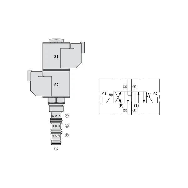
30SD08-47D Solenoid Directional Valve
Fiind unul dintre producătorii, furnizorii și exportatorii de cilindri hidraulici, oferim cilindri hidraulici și multe alte produse.
Vă rugăm să luați legătura cu noi pentru detalii.
Mail:sales@hydraulic-cylinders.net
Producător, furnizor, exportator de cilindri hidraulici.
30SD08-47D Solenoid Directional Valve
The 30SD08-47D Solenoid Directional Valve is a versatile and high-performance component designed for precise fluid control in various industrial applications. With its advanced features, durable construction, and reliable performance, this solenoid valve is an essential tool for optimizing fluid flow and enhancing operational efficiency. Whether in manufacturing, automation, or process control, the 30SD08-47D Solenoid Directional Valve offers superior functionality and versatility to meet the demanding requirements of modern industries.
The 30SD08-47D Solenoid Directional Valve is a reliable and versatile component that optimizes fluid control in various industrial applications. With its robust construction, precise fluid control, versatility, and space-efficient design, this solenoid valve offers exceptional performance, ensuring efficient and reliable operations. By incorporating the 30SD08-47D Solenoid Directional Valve into fluid control systems, industries can achieve enhanced productivity, accuracy, and system performance. Invest in this advanced solenoid valve to optimize your industrial processes, streamline operations, and achieve success in your industry.
30SD08-47D Solenoid Directional Valve Characteristics:
- Robust Construction: The 30SD08-47D Solenoid Directional Valve is built with a sturdy and durable design, ensuring longevity and reliability even in harsh operating conditions. Its robust construction allows it to withstand high pressure, temperature fluctuations, and challenging environments, providing consistent performance and minimizing downtime.
- Precise Fluid Control: This solenoid valve offers precise control over fluid flow, allowing for accurate and efficient regulation of media such as liquids and gases. With its responsive solenoid mechanism, the valve enables fast, reliable, and repeatable switching between different flow paths, facilitating smooth operations and enhancing productivity.
- Versatile Functionality: The 30SD08-47D Solenoid Directional Valve is designed to accommodate various applications across industries. It can be used for direction control, on/off switching, and pressure relief or regulation, providing flexibility and adaptability in fluid control systems.
- Compact and Space-Efficient: With its compact design, the solenoid valve occupies minimal space in industrial setups. This space-efficient feature is particularly beneficial in applications where installation space is limited, allowing for optimized system design and efficient utilization of available resources.
30SD08-47D Solenoid Directional Valve Parameter:
| Presiune nominală | 207 bari (3000 psi) | |
| Debit maxim | 11.4 L/min (3 gpm) | |
| Fluid | Pe bază de minerale sau sintetice cu proprietăți lubrifiante | |
| Interval de temperatură a fluidului ℃ | -54 până la 107 ℃ (Garnituri din poliuretan) | |
| -40 până la 100 ℃ (etanșări Buna N) | ||
| -26 până la 204 ℃ (etanșări cu fluorocarbon) | ||
| Interval de vâscozitate | 7,4 până la 420 mm2/s | |
| Gradul de contaminare | Nivelul minim de poluare este ISO4406 nivel 20/18/14, iar nivelul recomandat este 17/15/13 pentru a prelungi durata de viață. | |
| Scurgere internă | ≤ 164 mL/min@207bar | |
| Cavitate | VC08-4 | |
| Capacitate de încărcare a bobinei | Continuu de la 85% la 115% tensiune nominală | |
| Consum inițial de curent al bobinei la 20℃ | 1,4A la 12VDC; 0,7A la 24VDC | |
| Tensiune minimă de tragere | 85% de presiune nominală la 207 bar | |
30SD08-47D Solenoid Directional Valve Advantages:
• Bobină cu funcție continuă nominală
• Construcție eficientă cu armătură umedă
• Cartușele sunt interschimbabile la tensiune
• Bobine electronice opționale impermeabile, cu grad de protecție IP69K
• Piese călite pentru o durată lungă de viață
Usage Method Of 30SD08-47D Solenoid Directional Valve:
- Installation: Follow the manufacturer’s guidelines and specifications for proper installation of the 30SD08-47D Solenoid Directional Valve. Ensure correct alignment and connection with the fluid control system, using appropriate fittings and seals to maintain leak-free operation.
- Electrical Connections: Connect the solenoid valve to the power supply according to the specified voltage and electrical requirements. Ensure proper wiring and insulation to guarantee safe and reliable electrical operation.
- Fluid Flow Direction: Determine the desired fluid flow direction based on the requirements of your application. The solenoid valve offers different ports and positions for inlet, outlet, and exhaust, allowing for flexible configuration. Consult the product documentation for the correct port connections.
- Control Signal: Connect the control signal, typically electrical or pneumatic, to the solenoid valve to activate its switching mechanism. Ensure that the control signal is compatible with the valve’s specifications and operating parameters.
How To Hook Up A Hydraulic Flow Control Valve?
To hook up a hydraulic flow control valve, follow these steps:
- Identify Valve Type: Determine the specific type of flow control valve you are working with. Common types include needle valves, adjustable flow control valves, or pressure-compensated flow control valves. Ensure that the valve is suitable for your application and compatible with your hydraulic system.
- Gather Required Tools and Materials: Collect the necessary tools and materials, including appropriate hydraulic fittings, adapters, hoses, and wrenches.
- Pregătirea sistemului hidraulic: Shut down the hydraulic system and relieve any pressure in the system by activating the relief valve or retracting any hydraulic cylinders. This step is crucial for safety.
- Identify Flow Direction: Identify the flow direction in your hydraulic system. Typically, the flow direction is indicated by arrows on the hydraulic components. Ensure that you understand the correct flow direction before proceeding.
- Locate Installation Point: Determine the optimal location to install the flow control valve in your hydraulic system. Consider factors such as accessibility, proximity to the actuator or hydraulic component, and ease of adjustment.
- Montați valva: Securely mount the flow control valve in the chosen location using appropriate brackets or clamps. Ensure the valve is positioned correctly, aligning the inlet and outlet ports with the flow direction.
- Conectați orificiile de intrare și ieșire: Attach hydraulic hoses or tubing to the inlet and outlet ports of the flow control valve. Use suitable hydraulic fittings and adapters to create a leak-free connection. Tighten the connections using wrenches to ensure a secure fit, but avoid over-tightening.
- Adjust the Flow Control: Depending on the type of flow control valve, it may have adjustable features such as a needle valve or a flow control knob. Adjust the valve according to your desired flow rate or speed. Refer to the manufacturer’s instructions for specific adjustment procedures.
- Testați sistemul: Once the flow control valve is installed and adjusted, slowly restore hydraulic system pressure. Test the system to ensure that the flow control valve is functioning correctly. Monitor the flow rate or speed of the hydraulic actuator to verify that it is within the desired range.
- Fine-tune and Monitor: Adjust the flow control valve to achieve the desired flow rate or speed. Regularly monitor the hydraulic system for leaks, pressure inconsistencies, or unusual behavior.
Capabilitatea și capacitatea fabricii:
(1) Montaj
Avem o platformă de asamblare independentă de cercetare și dezvoltare de primă clasă. Atelierul de producție a cilindrilor hidraulici are patru linii de asamblare semiautomate pentru cilindri de ridicare și o linie de asamblare automată a cilindrilor de înclinare, cu o capacitate de producție anuală proiectată de 1 milion de bucăți. Atelierul de cilindri speciali este echipat cu diverse specificații ale unui sistem de asamblare semi-automat de curățare, cu o capacitate de producție anuală proiectată de 200.000 și dotat cu echipamente celebre de prelucrare CNC, un centru de prelucrare, un echipament special de prelucrare a cilindrilor de înaltă precizie, o mașină de sudură robotizată, o mașină de curățare automată, o mașină de asamblare automată a cilindrilor și o linie de producție automată de vopsire. Echipamente critice existente de peste 300 de seturi (seturi). Alocarea optimă și utilizarea eficientă a resurselor de echipamente asigură cerințele de precizie ale produselor și satisface nevoile de înaltă calitate ale produselor.


(2) Prelucrare
Atelierul de prelucrare este echipat cu un centru de strunjire cu șină înclinată personalizat, un centru de prelucrare, o mașină de honuire de mare viteză, un robot de sudură și alte echipamente conexe, care pot gestiona prelucrarea tuburilor cilindrice cu un diametru interior maxim de 400 mm și o lungime maximă de 6 metri.

(3) Sudură

(4) Vopsire și acoperire
Cu linii automate de acoperire cu vopsea pe bază de apă cu cilindru de dimensiuni mici și medii, pentru a realiza încărcarea și descărcarea automată a robotului și pulverizarea automată, capacitatea de proiectare de 4000 de bucăți pe schimb;
Avem, de asemenea, o linie de producție semi-automată de vopsire pentru cilindri mari, acționată de un lanț de putere, cu o capacitate de proiectare de 60 de cutii pe schimb.


(5) Testarea
Dispunem de instalații de inspecție și bancuri de testare de primă clasă pentru a ne asigura că performanța cilindrului îndeplinește cerințele.

Suntem unul dintre cei mai buni producători de cilindri hidraulici. Putem oferi o gamă completă de cilindri hidraulici. De asemenea, oferim... cutii de viteze agricoleNe-am exportat produsele către clienți din întreaga lume și ne-am câștigat o bună reputație datorită calității superioare a produselor noastre și a serviciilor post-vânzare. Îi invităm pe clienții din țară și din străinătate să ne contacteze pentru a negocia afaceri, a face schimb de informații și... să coopereze cu noi!
Cilindru hidraulic Aplicație:
