


4WRKE Series Pilot Operated Proportional Directional Hydraulic Valve
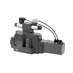

The 4WRKE series pilot-operated proportional directional hydraulic valve is a cutting-edge hydraulic component designed to provide superior precision, control, and efficiency in hydraulic systems. With its advanced pilot-operated proportional control technology, this valve enables accurate flow regulation and seamless directional changes.
The 4WRKE series pilot-operated proportional directional hydraulic valve empowers hydraulic systems with precise flow control, versatile directional changes, and energy efficiency. Its pilot-operated proportional control technology ensures accurate and responsive flow adjustment, while the high flow capacity guarantees reliable performance even in demanding applications. By following the recommended usage methods and maintenance guidelines, you can maximize the benefits and longevity of the 4WRKE series valve, elevating your hydraulic system to new levels of precision and control. Upgrade your hydraulic setup today and experience the power of the 4wrke series pilot-operated proportional directional hydraulic valve.
4WRKE Series Pilot Operated Proportional Directional Hydraulic Valve Key Characteristics:
- Pilot-Operated Proportional Control
- The 4WRKE series valve utilizes pilot-operated proportional control technology, allowing precise and proportional flow adjustment based on control signals.
- This feature ensures accurate and responsive control, resulting in improved system performance, reduced energy consumption, and enhanced productivity.
- Versatile Directional Control
- This valve offers versatile control over hydraulic fluid direction, making it suitable for a wide range of applications.
- It enables seamless activation and deactivation of hydraulic components such as cylinders, motors, and actuators in different directions, enhancing system flexibility and adaptability.
- High Flow Capacity
- The 4WRKE series valve is engineered to handle high flow rates, making it ideal for applications that require substantial hydraulic power.
- Its robust construction ensures reliable performance even under demanding conditions, providing consistent and efficient flow control.
- Eficiență energetică
- By incorporating pilot-operated proportional control, this valve minimizes pressure drops and optimizes energy usage.
- It helps reduce energy consumption, resulting in cost savings and environmental benefits.
4WRKE Series Pilot Operated Proportional Directional Hydraulic Valve Parameter:
| General | |||||||||
| Dimensiune | 10 | 16 | 25 | 27 | 32 | 35 | |||
| Installation and commissioning guidelines | opțional, de preferință orizontal | ||||||||
| Storage temperature range | ℃ | – 20 to + 80 | |||||||
| Ambient temperature range | ℃ | -20 to + 50 | |||||||
| Greutate | kg | 8.7 | 11.2 | 16.8 | 20 | 37.2 | 72 | ||
| Hidraulic ( measured at p=100bar,with HLP46 at ϑoil =40℃ ±5℃) | |||||||||
| Presiunea de funcționare | -Pilot control valve | Pilot oil supply | bar | 25 to 315 | |||||
| -Main valve | Port P A B | bar | Up to 315 | Up to 350 | Up to 350 | Up to 210 | Up to 350 | Up to 350 | |
| Return pressure | Portul T
(Pilot oil drain) |
Internal | bar | Static < 10 | |||||
| External | bar | Up to 315 | Up to 250 | Up to 250 | Up to 210 | Up to 250 | Up to 250 | ||
| Portul Y | bar | Static < 10 | |||||||
| Nominal flow qVnom ±10% at Δp=10bar (Δp = valve pressure differential) |
L/min | 25 50 | – 125 | – 220 | – – | – 440 | – | ||
| 100 | 180 | 350 | 500 | 600 | 1000 | ||||
| Flow of main valve (max. permissible) | L/min | 170 | 460 | 870 | 1000 | 1600 | 3000 | ||
| Pilot oil flow at port X or Y with a step form of input signal from 0 to 100 % (315 bar) | L/min | 4.1 | 8.5 | 11.7 | 11.7 | 13 | 13 | ||
| Pressure fluid | Mineral oil(HL,HLP)to DIN 51 524 Phosphate ester (HFD-R) | ||||||||
| Interval de temperatură al fluidului | ℃ | 10 to 80, preferably 40 to 50 | |||||||
| Interval de vâscozitate | mm2/s | 20 to 380, preferably 30 to 45 | |||||||
| Gradul de contaminare | Maximum permissible degree of contamination: NAS 1638. | A filter with a minimum retention rate of βx = 75 is recommended | |||||||
| Pilot control valve | Class 7 | x = 5 | |||||||
| Main valve | Class 9 | x = 7 | |||||||
| Histerezis | % | ≤1 | |||||||
| Sensibilitate la răspuns | % | ≤0,5 | |||||||
| Electrical | |||||||||
| Tip de tensiune | DC | ||||||||
| Conexiune electrică | Plug-in connector to DIN EN175 201-804 | ||||||||
| Power, max. | V | 72 (average = 24W) | |||||||
| Control electronics | Integrated into the valve | ||||||||
4WRKE Series Pilot Operated Proportional Directional Hydraulic Valve Advantages:
• Pilot-operated two-stage proportional directional valve with electrical position feedback of the main spool, used to control the size and direction of the liquid flow
• Sub-plate mounting type connection structure, connection size conforms to ISO 4401 standard
• Spring centred main spool
• With integrated proportional amplifier
• The pilot control is a single-stage proportional directional valve
• The pilot valve is a threaded proportional solenoid, and the coil can be disassembled separately
Usage Method Of 4WRKE Series Pilot Operated Proportional Directional Hydraulic Valve:
- System Evaluation
- Evaluate your hydraulic system and identify the specific flow and directional control requirements.
- Determine if the 4WRKE Series Valve is suitable based on its flow capacity, pressure rating, and compatibility with your system.
- Valve Selection
- Select the appropriate variant of the 4WRKE Series Valve based on your system parameters, flow requirements, and directional control needs.
- Luați în considerare factori precum debitul maxim, presiunea nominală, timpul de răspuns și condițiile de funcționare.
- Instalare
- Follow the manufacturer’s installation instructions carefully, ensuring proper alignment and secure mounting of the valve.
- Make leak-free connections and ensure the correct flow direction alignment to guarantee optimal performance.
- Control Signal Connection
- Connect the control signal wires of the valve to a suitable control device, such as a proportional amplifier or electronic control unit.
- Ensure proper wiring and compatibility between the valve and the control device for accurate and responsive control.
How To Clean Hydraulic Valve Lifters?
Cleaning hydraulic valve lifters is an important maintenance task that helps ensure proper engine performance and reduce noise caused by dirt or debris buildup. Here’s a step-by-step guide on how to clean hydraulic valve lifters:
- Adună instrumentele și materialele necesare:
- New engine oil
- Cârpe sau prosoape curate
- Engine degreaser or parts cleaner
- Small brush or toothbrush
- Plastic container or tray
- Preparare:
- Allow the engine to cool down completely before starting the cleaning process.
- Remove the valve cover or covers to access the hydraulic valve lifters. Refer to the manufacturer’s instructions or a repair manual for your specific engine to locate and remove the valve cover(s) properly.
- Removal of Hydraulic Valve Lifters:
- Identify the hydraulic valve lifters in the engine.
- One at a time, carefully remove the hydraulic valve lifters from their respective locations. Depending on your engine, you may need to remove other components or parts to access the lifters.
- Place each lifter in a plastic container or tray in the order they were removed. This will help ensure they are reinstalled correctly later.
- Cleaning the Lifters:
- Pour a small amount of engine degreaser or parts cleaner into a container.
- Place one hydraulic valve lifter into the container, ensuring it is fully submerged in the cleaner.
- Allow the lifter to soak for the recommended duration specified by the cleaner manufacturer. This usually ranges from 15 minutes to an hour.
- Use a small brush or toothbrush to gently scrub the lifter’s exterior surfaces, removing any deposits or dirt.
- Rinse the lifter thoroughly with clean water to remove any remaining cleaner or debris.
- Dry the lifter using a clean rag or towel. Ensure there are no traces of moisture before reinstallation.
- Reinstallation:
- Apply a small amount of fresh engine oil to the cleaned lifter’s exterior surface.
- Carefully place the lifter back into its original position in the engine, ensuring it is properly aligned and seated.
- Repeat the cleaning process for each hydraulic valve lifter, following the same steps.
- Once all the lifters are cleaned and reinstalled, make sure they are secured properly.
- Reasamblare:
- Reinstall the valve cover(s) according to the manufacturer’s instructions.
- Double-check that all components and parts are properly secured and tightened.
- Test and Inspection:
- Start the engine and let it run for a few minutes to ensure proper operation and to allow the lifters to refill with oil.
- Listen for any abnormal noises or ticking sounds that could indicate further issues.
- If noise or performance problems persist, it may be necessary to consult a professional mechanic for further diagnosis and repair.
Capabilitatea și capacitatea fabricii:
(1) Montaj
Avem o platformă de asamblare independentă de cercetare și dezvoltare de primă clasă. Atelierul de producție a cilindrilor hidraulici are patru linii de asamblare semiautomate pentru cilindri de ridicare și o linie de asamblare automată a cilindrilor de înclinare, cu o capacitate de producție anuală proiectată de 1 milion de bucăți. Atelierul de cilindri speciali este echipat cu diverse specificații ale unui sistem de asamblare semi-automat de curățare, cu o capacitate de producție anuală proiectată de 200.000 și dotat cu echipamente celebre de prelucrare CNC, un centru de prelucrare, un echipament special de prelucrare a cilindrilor de înaltă precizie, o mașină de sudură robotizată, o mașină de curățare automată, o mașină de asamblare automată a cilindrilor și o linie de producție automată de vopsire. Echipamente critice existente de peste 300 de seturi (seturi). Alocarea optimă și utilizarea eficientă a resurselor de echipamente asigură cerințele de precizie ale produselor și satisface nevoile de înaltă calitate ale produselor.


(2) Prelucrare
Atelierul de prelucrare este echipat cu un centru de strunjire cu șină înclinată personalizat, un centru de prelucrare, o mașină de honuire de mare viteză, un robot de sudură și alte echipamente conexe, care pot gestiona prelucrarea tuburilor cilindrice cu un diametru interior maxim de 400 mm și o lungime maximă de 6 metri.


(3) Sudură


(4) Vopsire și acoperire
Cu linii automate de acoperire cu vopsea pe bază de apă cu cilindru de dimensiuni mici și medii, pentru a realiza încărcarea și descărcarea automată a robotului și pulverizarea automată, capacitatea de proiectare de 4000 de bucăți pe schimb;
Avem, de asemenea, o linie de producție semi-automată de vopsire pentru cilindri mari, acționată de un lanț de putere, cu o capacitate de proiectare de 60 de cutii pe schimb.


(5) Testarea
Dispunem de instalații de inspecție și bancuri de testare de primă clasă pentru a ne asigura că performanța cilindrului îndeplinește cerințele.


Suntem unul dintre cei mai buni producători de cilindri hidraulici. Putem oferi o gamă completă de cilindri hidraulici. De asemenea, oferim... cutii de viteze agricoleNe-am exportat produsele către clienți din întreaga lume și ne-am câștigat o bună reputație datorită calității superioare a produselor noastre și a serviciilor post-vânzare. Îi invităm pe clienții din țară și din străinătate să ne contacteze pentru a negocia afaceri, a face schimb de informații și... să coopereze cu noi!