


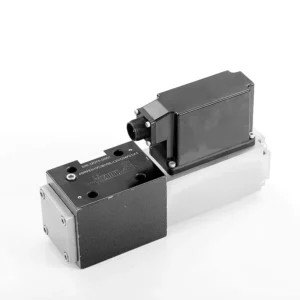
4WRPEH Series Proportional Directional Hydraulic Valve

The 4WRPEH series proportional directional hydraulic valve is an advanced hydraulic component designed to deliver exceptional precision and control in hydraulic systems. With its innovative proportional directional control technology, this valve enables accurate flow regulation and smooth directional changes.
The 4WRPEH series proportional directional hydraulic valve empowers hydraulic systems with precise flow control, versatile functionality, and enhanced efficiency. Its proportional directional control technology ensures accurate and responsive flow adjustment, while the high flow capacity guarantees reliable performance even in demanding applications. By following the recommended usage methods and maintenance guidelines, you can maximize the benefits and longevity of the 4WRPEH series valve, elevating your hydraulic system to new levels of precision and control. Upgrade your hydraulic setup today and experience the power of the 4WRPEH series proportional directional hydraulic valve.
4WRPEH Series Proportional Directional Hydraulic Valve Key Characteristics:
- Proportional Directional Control:
- The 4WRPEH series valve utilizes state-of-the-art proportional directional control technology, allowing precise and proportional flow adjustment based on control signals.
- This feature ensures accurate and responsive control, resulting in improved system performance, reduced energy consumption, and enhanced productivity.
- Funcționalitate versatilă:
- This valve offers versatile control over hydraulic fluid direction, making it suitable for a wide range of applications.
- It enables seamless activation and deactivation of hydraulic components such as cylinders, motors, and actuators in different directions, enhancing system flexibility and adaptability.
- Capacitate de debit mare:
- The 4WRPEH series valve is engineered to handle high flow rates, making it ideal for applications that require substantial hydraulic power.
- Its robust construction ensures reliable performance even under demanding conditions, providing consistent and efficient flow control.
- Precise Metering:
- With its proportional control technology, this valve offers precise metering of hydraulic fluid, allowing for accurate control and regulation of flow rates.
- This precision enhances overall system performance and ensures precise movements of hydraulic actuators.
4WRPEH Series Proportional Directional Hydraulic Valve Parameter:
NG6
| General | |||||||
| Proiecta | Spool valve, direct operated, with steel sleeve | ||||||
| Actuation | Proportional solenoid with position control, OBE | ||||||
| Connection type | Subplate mounting, porting pattern according to ISO 4401-03-02-0-05 | ||||||
| Poziția de instalare | Any | ||||||
| Ambient temperature range | ℃ | -20…+50 | |||||
| Greutate | Kg | about 2.75 | |||||
| Maximum vibration resistance (test condition) | Max. 25 g, space vibration test in all directions (24h) | ||||||
| Hidraulic (measured at p=100bar, with HLP46 at ϑoil = 40℃ ±5℃) | |||||||
| Pressure fluid | Mineral oil (HL, HLP)to DIN 51 524 | ||||||
| Interval de vâscozitate | recommended | mm²/s | 20…100 | ||||
| max. permitted | mm²/s | 10…800 | |||||
| Pressure fluid temperature range | ℃ | -20 to +70 | |||||
| Maximum permitted degree of contamination of pressure fluid Purity class to ISO 4406 (c) | Class 18/16/13 | ||||||
| Rated flow (Δp = 35 bar per edge) | L/min | 2 | 4 | 12 | 24 | 40 | |
| Presiune maximă de funcționare | bar | Port A、B、P:315 | |||||
| Max. pressure | bar | Port T: 250 | |||||
| Leakage flow at 100 bar | Linear | cm³/min | <150 | <180 | <300 | <500 | <900; |
| Nonlinear | cm³/min | / | / | / | <300 | <450; | |
| Static/Dynamic | |||||||
| Histerezis | % | ≤0.2 | |||||
| Actuating time for signal step 0 … 100% | Domnișoară | 10 | |||||
| Temperature drift | Zero shift < 1% at ΔT=40℃ | ||||||
| Zero compensation | Ex factory ±1% | ||||||
| Electric, control electronics integrated in the valve | |||||||
| Relative duty cycle | % | 100ED | |||||
| Degree of protection | IP65 | ||||||
| Connection | Plug-in connector 6P+PE, DIN 43563 | ||||||
| Supply voltage Terminal A Terminal B |
24VDCnom | ||||||
| min. 21VDC / max. 40VDC | |||||||
| 0V (ripple max. 2) | |||||||
| Fuse protection, external | AF | 2.5 | |||||
| nput, version “A1” Terminal D (UE) Terminal E |
Differential amplifier, Ri = 100 kΩ | ||||||
| 0…±10V | |||||||
| 0V | |||||||
| Input, version “F1” Terminal D (ID-E) Terminal E (ID-E) |
Load, Rsh = 200 Ω | ||||||
| 4…12…20mA | |||||||
| Current loop ID-E return | |||||||
| Test signal, version “A1” Terminal F (UTest) Terminal C |
LVDT | ||||||
| 0…±10V | |||||||
| Reference 0 V | |||||||
| Test signal, version “F1” Terminal F ( I F-C ) Terminal C ( I F-C ) |
LVDT signal 4 … (12) … 20 mA on external load 200 … 500 Ωmaximum | ||||||
| 4 … (12) … 20mA (output) | |||||||
| Current loop IF-C return | |||||||
| Adjustment | Calibrated before delivery, see characteristic curves | ||||||
NG10
| General | |||||
| Proiecta | Spool valve, directly operated, with steel sleeve | ||||
| Actuation | Proportional solenoid with position control, OBE | ||||
| Connection type | Plate port, porting pattern (ISO 4401-05-04-0-05) | ||||
| Poziția de instalare | Any | ||||
| Interval de temperatură în circumstanțe | ℃ | -20…+50 | |||
| Greutate | Kg | about 7.1 | |||
| Maximum vibration resistance (test condition) | Max. 25 g, space vibration test in all directions (24h) | ||||
| Hydraulic (measured with HLP 46, ϑoil =40℃ ±5℃) | |||||
| Pressure fluid | Hydraulic oil according to DIN 51524…535 | ||||
| Interval de vâscozitate | recommended | mm²/s | 20…100 | ||
| Max. permitted | mm²/s | 10…800 | |||
| Pressure fluid temperature range | ℃ | -20 to +70 | |||
| Max. admissible degree of contamination of the hydraulic fluid,cleanliness class according to ISO 4406 (c) | Class 18/16/13 | ||||
| Rated flow(Δp = 35 bar per edge) | L/min | 50 | 100 | ||
| Presiune maximă de funcționare | bar | Port P A B: 315 | |||
| Max. pressure | bar | Port T: 250 | |||
| Leakage flow at 100 bar | Linear | cm³/min | <1200 | <1500 | |
| Nonlinear | cm³/min | <600 | <600 | ||
| Static/Dynamic | |||||
| Histerezis | % | ≤0.2 | |||
| Actuating time for signal step 0 … 100% | Domnișoară | 25 | |||
| Temperature drift | Zero shift < 1% at ΔT=40℃ | ||||
| Zero compensation | Ex factory ±1% | ||||
| Electric, control electronics integrated in the valve | |||||
| Relative duty cycle | % | 100ED | |||
| Degree of protection | IP65(with mating connector mounted and locked ) | ||||
| Connection | Mating connector 6P+PE, DIN 43563 | ||||
| Supply voltage Terminal A Terminal B |
24VDCnom | ||||
| min. 21VDC / max. 40VDC | |||||
| Ripple max. 2 VDC | |||||
| Fuse protection, external | AF | 2.5 | |||
| Input, version “A1” Terminal D (UE) Terminal E |
Differential amplifier, Ri = 100 kΩ | ||||
| 0…±10V | |||||
| 0V | |||||
| Input, version “F1” Terminal D (ID-E) Terminal E (ID-E) |
Load, Rsh = 200 | ||||
| 4…12…20mA | |||||
| Current loop ID-E return | |||||
| Test signal, version “A1” Terminal F (UTest) Terminal C |
LVDT | ||||
| 0…±10V | |||||
| Reference 0 V | |||||
| Test signal, version “F1” Terminal F ( I F-C ) Terminal C ( I F-C ) |
LVDT | ||||
| 4…20 mA output | |||||
| Current loop IF-C feedback | |||||
4WRPEH Series Proportional Directional Hydraulic Valve Advantages:
• Direct-acting servo solenoid valve with control piston and valve sleeve, with servo performance
• Single-side drive, optional with power-off safety function
Control solenoid with built-in feedback and integrated amplifier board (OBE), factory preset
• Electrical connection 6P+PE signal input differential amplifier with interface, input optional A1: ±10V, or interface F1: 4…20mA (Rsh =200Ω)
• Panel mounting, the mounting surface complies with ISO 4401-03-02
Usage Method Of 4WRPEH Series Proportional Directional Hydraulic Valve :
- Evaluarea sistemului:
- Evaluate your hydraulic system and identify the specific flow and directional control requirements.
- Determine if the 4WRPEH series valve is suitable based on its flow capacity, pressure rating, and compatibility with your system.
- Selectarea supapelor:
- Select the appropriate variant of the 4WRPEH series valve based on your system parameters, flow requirements, and directional control needs.
- Luați în considerare factori precum debitul maxim, presiunea nominală, timpul de răspuns și condițiile de funcționare.
- Instalare:
- Follow the manufacturer’s installation instructions carefully, ensuring proper alignment and secure mounting of the valve.
- Make leak-free connections and ensure correct flow direction alignment to guarantee optimal performance.
- Conexiune semnal de control:
- Connect the control signal wires of the valve to a suitable control device, such as a proportional amplifier or electronic control unit.
- Ensure proper wiring and compatibility between the valve and the control device for accurate and responsive control.
How To Hook Two Hydraulic Valves Together?
Hooking two hydraulic valves together requires careful consideration of the valve types, their functions, and the specific hydraulic system requirements. Here are general guidelines on how to hook two hydraulic valves together:
- Identify Valve Types:
- Determine the types of valves you are working with, such as directional control valves, pressure control valves, flow control valves, or any other specific valves required for your system.
- Ensure that both valves are compatible in terms of size, pressure ratings, flow capacity, and function.
- Understand Valve Functions:
- Familiarize yourself with the functions of each valve. For example, directional control valves regulate fluid flow direction, pressure control valves control system pressure, and flow control valves manage flow rates.
- Determine how the combination of these valves will contribute to achieving the desired hydraulic system operation.
- Determine Valve Placement:
- Decide where in the hydraulic system you want to install the two valves. Consider factors such as fluid flow path, pressure requirements, and the desired control sequence.
- Ensure that the valve placement allows for proper fluid flow and accessibility for maintenance and operation.
- Connect Valve Ports:
- Identify the inlet and outlet ports of each valve. These ports may be labeled or indicated in the valve documentation.
- Use appropriate hydraulic fittings, adapters, or connectors to connect the ports of the two valves together.
- Ensure a secure and leak-free connection by using suitable sealing materials, such as O-rings or thread sealants.
- Consider Valve Interactions:
- Evaluate how the interaction between the two valves will affect the hydraulic system’s overall performance.
- Ensure that the combined operation of the valves does not create conflicts or result in unintended consequences, such as pressure spikes, flow restrictions, or unintended movements.
- Control Signal Integration:
- If the valves require control signals, such as electrical or pneumatic signals, determine how these signals will be integrated.
- Connect the control signal lines of both valves to the appropriate control devices, such as hydraulic control modules, electronic control units, or manual control levers.
- Ensure proper wiring, compatibility, and synchronization between the control devices and the valves to achieve the desired control and coordination.
- Test and Adjust:
- After hooking the valves together, thoroughly test the hydraulic system to ensure proper operation.
- Monitor the system for any issues, such as leaks, excessive pressure drops, or unexpected behavior.
- Make necessary adjustments, such as fine-tuning control settings or modifying valve placement if required.
Capabilitatea și capacitatea fabricii:
(1) Montaj
Avem o platformă de asamblare independentă de cercetare și dezvoltare de primă clasă. Atelierul de producție a cilindrilor hidraulici are patru linii de asamblare semiautomate pentru cilindri de ridicare și o linie de asamblare automată a cilindrilor de înclinare, cu o capacitate de producție anuală proiectată de 1 milion de bucăți. Atelierul de cilindri speciali este echipat cu diverse specificații ale unui sistem de asamblare semi-automat de curățare, cu o capacitate de producție anuală proiectată de 200.000 și dotat cu echipamente celebre de prelucrare CNC, un centru de prelucrare, un echipament special de prelucrare a cilindrilor de înaltă precizie, o mașină de sudură robotizată, o mașină de curățare automată, o mașină de asamblare automată a cilindrilor și o linie de producție automată de vopsire. Echipamente critice existente de peste 300 de seturi (seturi). Alocarea optimă și utilizarea eficientă a resurselor de echipamente asigură cerințele de precizie ale produselor și satisface nevoile de înaltă calitate ale produselor.


(2) Prelucrare
Atelierul de prelucrare este echipat cu un centru de strunjire cu șină înclinată personalizat, un centru de prelucrare, o mașină de honuire de mare viteză, un robot de sudură și alte echipamente conexe, care pot gestiona prelucrarea tuburilor cilindrice cu un diametru interior maxim de 400 mm și o lungime maximă de 6 metri.


(3) Sudură


(4) Vopsire și acoperire
Cu linii automate de acoperire cu vopsea pe bază de apă cu cilindru de dimensiuni mici și medii, pentru a realiza încărcarea și descărcarea automată a robotului și pulverizarea automată, capacitatea de proiectare de 4000 de bucăți pe schimb;
Avem, de asemenea, o linie de producție semi-automată de vopsire pentru cilindri mari, acționată de un lanț de putere, cu o capacitate de proiectare de 60 de cutii pe schimb.


(5) Testarea
Dispunem de instalații de inspecție și bancuri de testare de primă clasă pentru a ne asigura că performanța cilindrului îndeplinește cerințele.


Suntem unul dintre cei mai buni producători de cilindri hidraulici. Putem oferi o gamă completă de cilindri hidraulici. De asemenea, oferim... cutii de viteze agricoleNe-am exportat produsele către clienți din întreaga lume și ne-am câștigat o bună reputație datorită calității superioare a produselor noastre și a serviciilor post-vânzare. Îi invităm pe clienții din țară și din străinătate să ne contacteze pentru a negocia afaceri, a face schimb de informații și... să coopereze cu noi!