Supapă hidraulică de accelerație și de verificare a accelerației din seria MG/MK
Supapă hidraulică de accelerație și de verificare a accelerației din seria MG/MK
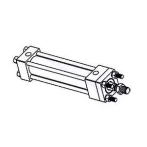
Supapa hidraulică de accelerație și de verificare a accelerației din seria MG/MK este o componentă hidraulică versatilă și de înaltă performanță, concepută pentru a optimiza controlul și eficiența în sistemele hidraulice. Cu funcționalitatea sa unică de accelerație și verificare a accelerației, această supapă oferă un control precis al debitului și asigură funcționarea lină a actuatoarelor hidraulice.
Supapa hidraulică de accelerație și de control al accelerației din seria MG/MK este o soluție versatilă și fiabilă pentru un control precis al debitului și o eficiență sporită a sistemului. Cu funcționalitatea sa de accelerație, funcția de verificare a accelerației și opțiunile personalizabile de control al debitului, această supapă oferă performanțe excepționale în diverse aplicații hidraulice. Urmând metodele de utilizare recomandate și instrucțiunile de întreținere, operatorii pot asigura longevitatea, fiabilitatea și funcționalitatea optimă a supapei hidraulice de accelerație și de control din seria MG/MK. Modernizați-vă sistemul hidraulic cu această supapă avansată și experimentați un control, o eficiență și o productivitate îmbunătățite.
Caracteristici cheie ale clapetei de accelerație și supapei hidraulice de verificare a clapetei de accelerație din seria MG/MK:
- Funcționalitatea accelerației:
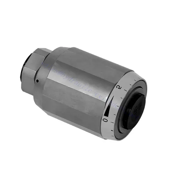
- Supapa din seria MG/MK dispune de o funcție de accelerație care reglează debitul fluidului hidraulic.
- Permite controlul precis al debitului de fluid, permițând reglarea fină a vitezei și a răspunsului actuatorului.
- Funcția de verificare a clapetei de accelerație:
- Pe lângă controlul clapetei de accelerație, această supapă încorporează o funcție de verificare a clapetei de accelerație.
- Funcția de verificare a clapetei de accelerație permite supapei să acționeze ca o supapă de sens unidirecțional, prevenind curgerea inversă și menținând stabilitatea sistemului.
- Versatilitate în controlul fluxului:
- Valva din seria MG/MK oferă o gamă largă de opțiuni de control al debitului, permițând personalizarea pentru a se potrivi cerințelor specifice ale aplicației.
- Poate fi configurat pentru debite variabile, diferențe de presiune și dimensiuni ale actuatoarelor, asigurând compatibilitatea cu diverse sisteme hidraulice.
- Eficiență îmbunătățită a sistemului:
- Prin asigurarea unui control precis al debitului, valva minimizează pierderile de energie și optimizează eficiența generală a sistemului.
- Permite operatorilor să adapteze debitul hidraulic la cerințele specifice de sarcină, reducând consumul inutil de energie.
- Performanță fiabilă:
- Valva din seria MG/MK este construită pentru a rezista la condiții dificile de funcționare și a oferi performanțe constante.
- Construcția robustă și materialele de înaltă calitate asigură durabilitate și fiabilitate în diverse aplicații.
Parametrul supapei hidraulice de accelerație și de verificare a accelerației din seria MG/MK:
| Dimensiune | 6 | 8 | 10 | 15 | 20 | 25 | 30 | |
| Greutate | kg | 0.3 | 0.4 | 0.7 | 1.3 | 2.2 | 3.6 | 4.5 |
| Presiune maximă de funcționare | bar | 315 bari | ||||||
| Presiune de deschidere pentru tipul MK | bar | 0.5 | ||||||
| Debit maxim | L/min | 400 | ||||||
| Interval de vâscozitate | mm2/s | 10 până la 800 | ||||||
| Interval de temperatură al fluidului | ℃ | -30℃ până la +80℃ | ||||||
| Fluid | Ulei mineral; Ester fosfat | |||||||
| Gradul de contaminare | Grad maxim admis de contaminare a fluidului: Clasa 9. NAS 1638 sau 20/18/15, ISO4406 | |||||||
Avantajele supapelor hidraulice de accelerație și de verificare a accelerației din seria MG/MK:
• Utilizat în instalarea directă a tubulaturii
• Legat de presiune și vâscozitate
Metoda de utilizare a clapetei de accelerație și a supapei hidraulice de verificare a clapetei de accelerație din seria MG/MK:
- Evaluarea sistemului:
- Assess the hydraulic system’s requirements, including flow rates, pressure differentials, and actuator specifications.
- Identificați necesitatea clapetei de accelerație și a funcționalității de verificare a clapetei de accelerație în sistem.
- Selectarea supapelor:
- Selectați varianta corespunzătoare a valvei din seria MG/MK pe baza parametrilor sistemului și a caracteristicilor de control al debitului dorite.
- Luați în considerare factori precum debitul maxim, presiunea nominală și compatibilitatea cu alte componente ale sistemului.
- Instalare:
- Follow the manufacturer’s installation instructions and ensure proper alignment and connection of the valve.
- Acordați atenție săgeților care indică direcția de curgere și asigurați-vă că fitingurile și etanșările sunt fixate.
- Reglarea debitului:
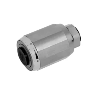
- Reglați setarea clapetei de accelerație de pe supapă pentru a obține debitul dorit.
- Reglați fin controlul clapetei de accelerație pentru a optimiza performanța actuatorului și eficiența sistemului.
Cum funcționează supapa de control hidraulic?
O supapă de control hidraulic este o componentă critică în sistemele hidraulice care reglează debitul și presiunea fluidului hidraulic. Aceasta servește ca mecanism de control pentru direcționarea fluidului către diferite actuatoare hidraulice și controlul vitezei și direcției mișcării acestora. Funcționarea unei supape de control hidraulic poate fi descrisă după cum urmează:
- Structura valvei:
- O supapă de control hidraulic cuprinde un corp de supapă care găzduiește diverse componente interne, cum ar fi bobine, clapete sau discuri.
- Corpul valvei conține orificii, pasaje și camere care facilitează curgerea fluidului hidraulic.
- Pozițiile supapelor:
- Supapele de control hidraulic au de obicei mai multe poziții, inclusiv deschisă, închisă și parțial deschisă.
- În poziția închisă, supapa blochează complet curgerea fluidului.
- În poziția deschisă, supapa permite fluidului să curgă liber prin orificii specifice.
- În poziția parțial deschisă, supapa restricționează sau controlează debitul fluidului.
- Funcționarea supapei hidraulice:
- Valvele hidraulice sunt utilizate în mod obișnuit în sistemele de control hidraulic. Acestea constau dintr-o bobină cilindrică cu canale sau zone de legătură.
- Bobina este poziționată în corpul valvei și poate fi deplasată longitudinal.
- Prin deplasarea bobinei, diferite zone se aliniază cu orificii specifice, permițând sau blocând curgerea fluidului către diferiți actuatori.
- Mișcarea bobinei se realizează de obicei folosind legături mecanice, solenoizi sau presiune hidraulică care acționează asupra bobinei.
- Funcționarea supapei cu clapetă:
- Supapele cu clapetă sunt un alt tip de supapă de control hidraulic. Acestea utilizează o clapetă sau un disc mobil pentru a controla debitul de fluid.
- Când clapeta este în poziția închisă, aceasta se sprijină pe un scaun, blocând curgerea fluidului.
- Pentru a deschide supapa, clapeta este deplasată departe de scaun, permițând fluidului să curgă prin pasaj.
- Mișcarea șurubului poate fi realizată prin legături mecanice sau presiune hidraulică.
- Mecanisme de control:
- Supapele de control hidraulic pot fi acționate manual, mecanic sau prin mijloace electrice.
- Controlul manual implică utilizarea unor pârghii, butoane sau mânere pentru a poziționa elementul supapei.
- Controlul mecanic utilizează legături mecanice sau actuatoare pentru a mișca elementul supapei.
- Controlul electric utilizează solenoizi sau alte dispozitive controlate electric pentru a deplasa elementul supapei.
- Controlul actuatorului:
- Supapele de control hidraulic direcționează fluidul către diverse actuatoare hidraulice, cum ar fi cilindrii sau motoarele.
- Prin controlul pozițiilor supapelor, sistemul hidraulic poate regla viteza, direcția și forța actuatoarelor.
- De exemplu, reglarea poziției supapei poate controla extensia sau retragerea unui cilindru hidraulic.
- Stabilitatea și siguranța sistemului:
- Supapele de control hidraulic joacă un rol crucial în menținerea stabilității și siguranței sistemului.
- Supapele de suprapresiune sunt adesea încorporate în sistemele de control hidraulic pentru a proteja împotriva suprapresiunii.
- Aceste supape de siguranță deviază excesul de fluid către o ieșire de joasă presiune, prevenind deteriorarea sistemului.
Capabilitatea și capacitatea fabricii:
(1) Montaj
Avem o platformă de asamblare independentă de cercetare și dezvoltare de primă clasă. Atelierul de producție a cilindrilor hidraulici are patru linii de asamblare semiautomate pentru cilindri de ridicare și o linie de asamblare automată a cilindrilor de înclinare, cu o capacitate de producție anuală proiectată de 1 milion de bucăți. Atelierul de cilindri speciali este echipat cu diverse specificații ale unui sistem de asamblare semi-automat de curățare, cu o capacitate de producție anuală proiectată de 200.000 și dotat cu echipamente celebre de prelucrare CNC, un centru de prelucrare, un echipament special de prelucrare a cilindrilor de înaltă precizie, o mașină de sudură robotizată, o mașină de curățare automată, o mașină de asamblare automată a cilindrilor și o linie de producție automată de vopsire. Echipamente critice existente de peste 300 de seturi (seturi). Alocarea optimă și utilizarea eficientă a resurselor de echipamente asigură cerințele de precizie ale produselor și satisface nevoile de înaltă calitate ale produselor.


(2) Prelucrare
Atelierul de prelucrare este echipat cu un centru de strunjire cu șină înclinată personalizat, un centru de prelucrare, o mașină de honuire de mare viteză, un robot de sudură și alte echipamente conexe, care pot gestiona prelucrarea tuburilor cilindrice cu un diametru interior maxim de 400 mm și o lungime maximă de 6 metri.

(3) Sudură

(4) Vopsire și acoperire
Cu linii automate de acoperire cu vopsea pe bază de apă cu cilindru de dimensiuni mici și medii, pentru a realiza încărcarea și descărcarea automată a robotului și pulverizarea automată, capacitatea de proiectare de 4000 de bucăți pe schimb;
Avem, de asemenea, o linie de producție semi-automată de vopsire pentru cilindri mari, acționată de un lanț de putere, cu o capacitate de proiectare de 60 de cutii pe schimb.


(5) Testarea
Dispunem de instalații de inspecție și bancuri de testare de primă clasă pentru a ne asigura că performanța cilindrului îndeplinește cerințele.

Suntem unul dintre cei mai buni producători de cilindri hidraulici. Putem oferi o gamă completă de cilindri hidraulici. De asemenea, oferim... cutii de viteze agricoleNe-am exportat produsele către clienți din întreaga lume și ne-am câștigat o bună reputație datorită calității superioare a produselor noastre și a serviciilor post-vânzare. Îi invităm pe clienții din țară și din străinătate să ne contacteze pentru a negocia afaceri, a face schimb de informații și... să coopereze cu noi!