
WEH Series Directional Hydraulic Valves Of Pilot Operated
Fiind unul dintre producătorii, furnizorii și exportatorii de cilindri hidraulici, oferim cilindri hidraulici și multe alte produse.
Vă rugăm să luați legătura cu noi pentru detalii.
Mail:sales@hydraulic-cylinders.net
Producător, furnizor, exportator de cilindri hidraulici.
WEH Series Directional Hydraulic Valves Of Pilot Operated
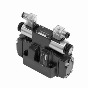
The WEH series directional hydraulic valves of pilot operated are advanced components that provide precise and efficient control over hydraulic systems. Designed to meet the demands of various industries, these valves offer exceptional performance, reliability, and versatility.
The WEH series directional hydraulic valves of pilot operated are reliable, high-performance components that empower operators with precise control and efficient fluid management in hydraulic systems. With their pilot-operated design, exceptional directional control, a wide range of configurations, and high flow capacity, these valves offer the reliability and versatility required in various industries. Following the recommended usage methods and adhering to regular maintenance practices, the WEH series valves will continue delivering exceptional performance. Upgrade your hydraulic system with the WEH series directional hydraulic valves operated and experience the benefits of precision, control, and reliability.
WEH Series Directional Hydraulic Valves Of Pilot Operated Key Characteristics:
- Design acționat de pilot:
- The WEH series valves utilize a pilot-operated design, which enhances their responsiveness and control accuracy.
- This design enables the valves to handle high-pressure applications, ensuring optimal performance easily.
- Control direcțional:
- These hydraulic valves excel in providing precise directional control of hydraulic fluid.
- Operators can easily manage fluid flow and direct it to different actuators or components within the hydraulic system.
- Wide Range of Configurations:
- The WEH series valves are available in various configurations, including various sizes, flow rates, and pressure ratings.
- This versatility allows them to be tailored to specific application requirements and system specifications.
- Capacitate de debit mare:
- These valves are designed to handle high flow rates, making them suitable for applications that demand substantial fluid flow.
- Their optimized internal passages and robust construction ensure minimal pressure drop and efficient fluid management.
WEH Series Directional Hydraulic Valves Of Pilot Operated Parameter:
NG10
| Specificații | WEH10 type | |||||||||
| Max. operating pressure:P、A、B | 350 | |||||||||
| Portul T | With external pilot oil drain bar | 315 | ||||||||
| With internal pilot oil drain bar | DC 210 AC 160 | |||||||||
| Portul Y | With external pilot oil drain bar | DC 210 AC 160 | ||||||||
| Min. control pressure | With external pilot oil supply ( not apply to C、Z、 F、G、H、P、T、V) bar |
3-position valve 10 | ||||||||
| Spring-return 2-position valve 10 | ||||||||||
| Hydraulic-return 2-position valve 7 | ||||||||||
| With internal pilot oil supply ( apply to C、Z、F、 G、H、P、T、V) bar |
6.5 | |||||||||
| Max. control pressure bar | 250 | |||||||||
| Fluid | Mineral oil,Phosphate ester | |||||||||
| Fluid temperature range ℃ | -30 to +80 ( NBR seals | |||||||||
| -20 to +80 ( FKM seals ) | ||||||||||
| Viscosity range mm2/s | 2,8 până la 500 | |||||||||
| Switching pilot oil volume cm3 | 3-position valve 2.04 | |||||||||
| 2-position valve 4.08 | ||||||||||
| Switching times (= Valve switching time from the neutral position to the switched position)(AC and DC ) | ||||||||||
| Control pressure bar | 70 | 140 | 210 | 250 | ||||||
| AC | DC | AC | DC | AC | DC | AC | DC | |||
| 3-position valve ms | 30 | 65 | 25 | 60 | 20 | 55 | 15 | 50 | ||
| 2-position valve ms | 35 | 80 | 30 | 75 | 25 | 70 | 20 | 65 | ||
| Switching times (= Valve switching time from the switched position to the neutral position) | ||||||||||
| 3-position valve ms | 30 | |||||||||
| 2-position valve ms | 35 | 40 | 30 | 35 | 25 | 30 | 20 | 25 | ||
| Poziția de instalare | HC、HD、HK、HZ、HY Type hydraulic-return valves are installed horizontally, the rest can be installed arbitrarily | |||||||||
| Flow of shortest switching time L/min | about 35 | |||||||||
| Greutate | Single solenoid valve kg | 6.7 | ||||||||
| Double solenoid valve kg | 7.1 | |||||||||
| Switching time regulator kg | 1.0 | |||||||||
| Reducing valve kg | 0.5 | |||||||||
NG16
| Specificații | WEH16… type | |||||||||||||
| Max. operating pressure:P、A、B | 350 | |||||||||||||
| Portul T | With external pilot oil drain bar | 250 | ||||||||||||
| With internal pilot oil drain bar | DC 210 AC 160 | |||||||||||||
| Portul Y | With external pilot oil drain bar | DC 210 AC 160 | ||||||||||||
| Min. control pressure | With external pilot oil supply ( not apply to C、Z、 F、G、H、P、T、V)bar |
3-position valve 14 | ||||||||||||
| Spring-return 2-position valve 14 | ||||||||||||||
| Hydraulic-return 2-position valve 14 | ||||||||||||||
| With internal pilot oil supply ( apply to C、Z、F、 G、 H、P、T、V) bar |
When applying prepressing or the flow is large correspondingly ,enginery of spool valve is 4.5 as C,Z,F,G,H,P,T and V | |||||||||||||
| Max. control pressure bar | 250 | |||||||||||||
| Fluid | Mineral oil,Phosphate ester | |||||||||||||
| Fluid temperature range ℃ | -30 to +80 ( NBR seals | |||||||||||||
| -20 to +80 ( FKM seals ) | ||||||||||||||
| Viscosity range mm2/s | 2,8 până la 500 | |||||||||||||
| Switching pilot oil volume | ||||||||||||||
| – Spring-centering 3-position valve cm3 | 5.72 | |||||||||||||
| – 2-position valve cm3 | 11.45 | |||||||||||||
| * * Switching times (= Valve switching time from the neutral position to the switched position)(AC and DC) | ||||||||||||||
| Control pressure bar | 50 | 150 | 250 | |||||||||||
| AC | DC | AC | DC | AC | DC | AC | DC | AC | DC | AC | DC | |||
| – Spring-centering 3-position valve ms | 35 | 65 | 30 | 60 | 30 | 58 | ||||||||
| – 2-position valve ms | 45 | 65 | 35 | 55 | 30 | 50 | ||||||||
| **Switching times (= Valve switching time from the neutral position to the switched position) | ||||||||||||||
| – Spring-centering 3-position valve ms | 30 | |||||||||||||
| – 2-position valve ms | 45 | 45 | 35 | 35 | 30 | 30 | ||||||||
| Poziția de instalare | C,D,K,Z,Y Type hydraulic-return valves are installed horizontally, the rest can be installed arbitrarily | |||||||||||||
| Flow of shortest switching time L/min | about 35 | |||||||||||||
| Weight kg | about 9.5 | |||||||||||||
NG25
| Specificații | WEH25… type | |||||||||||||||||
| Max. operating pressure:P、A、B | 350 | |||||||||||||||||
| Portul T | With external pilot oil drain bar | 250 | ||||||||||||||||
| With internal pilot oil drain bar | DC 210 AC 160 | |||||||||||||||||
| Portul Y | With external pilot oil drain bar | DC 210 AC 160 | ||||||||||||||||
| Min. control pressure | With external pilot oil supply ( not apply to C、Z、F、 G、H、P、T、V) bar |
Spring-centering 3-position valve 13 | ||||||||||||||||
| Spring-return 2-position valve 13 | ||||||||||||||||||
| Hydraulic-return 2-position valve 8 | ||||||||||||||||||
| With internal pilot oil supply ( apply to C、Z、F、 G、H、P、T、V) bar |
When applying prepressing or the flow is large correspondingly ,enginery of spool valve is 4.5 as C,Z,F,G,H,P,T and V | |||||||||||||||||
| Max. control pressure bar | 250 | |||||||||||||||||
| Fluid | Mineral oil,Phosphate ester | |||||||||||||||||
| Fluid temperature range ℃ | -30 to +80 ( NBR seals | |||||||||||||||||
| -20 to +80 ( FKM seals ) | ||||||||||||||||||
| Switching pilot oil volume | ||||||||||||||||||
| – Spring-centering 3-position valve cm3 | 14.2 | |||||||||||||||||
| – 2-position valve cm3 | 28.4 | |||||||||||||||||
| * Switching times (= Valve switching time from the neutral position to the switched position)(AC and DC) | ||||||||||||||||||
| Control pressure bar | 50 | 140 | 210 | 250 | ||||||||||||||
| AC | DC | AC | DC | AC | DC | AC | DC | |||||||||||
| – Spring-centering 3-position valve ms | 50 | 85 | 40 | 75 | 35 | 70 | 30 | 65 | ||||||||||
| – 2-position valve ms | 120 | 160 | 100 | 130 | 85 | 120 | 70 | 105 | ||||||||||
| *Switching times (= Valve switching time from the neutral position to the switched position) | ||||||||||||||||||
| – Spring-centering 3-position valve ms | 40 | |||||||||||||||||
| – 2-position valve ms | 120 | 125 | 95 | 100 | 85 | 90 | 75 | 80 | ||||||||||
| Poziția de instalare | C,D,K,Z,Y Type hydraulic-return valves are installed horizontally, the rest can be installed arbitrarily | |||||||||||||||||
| Flow of shortest switching time L/min | about 35 | |||||||||||||||||
| Weight kg | about 18 | |||||||||||||||||
NG32
| Specificații | WEH32… type | |||||||||||||
| Max. operating pressure:P、A、B | 350 | |||||||||||||
| Portul T | With external pilot oil drain bar | 250 | ||||||||||||
| With internal pilot oil drain bar | DC 210 AC 160 | |||||||||||||
| Portul Y | With external pilot oil drain bar | DC 210 AC 160 | ||||||||||||
| Min. control pressure | With external pilot oil supply
With internal pilot oil supply |
3-position valve 8.5 | ||||||||||||
| Spring-return 2-position valve 10 | ||||||||||||||
| Hydraulic-return 2-position valve 15 | ||||||||||||||
| With internal pilot oil supply ( apply to C、Z、F、 G、H、P、T、V) bar |
When applying prepressing or the flow is large correspondingly ,enginery of spool valve is 4.5 as C,Z,F,G,H,P,T and V | |||||||||||||
| Max. control pressure bar | 250 | |||||||||||||
| Fluid | Mineral oil,Phosphate ester | |||||||||||||
| Fluid temperature range ℃ | -30 to +80 ( NBR seals | |||||||||||||
| -20 to +80 ( FKM seals ) | ||||||||||||||
| Viscosity range mm2/s | 2,8 până la 500 | |||||||||||||
| Switching pilot oil volume | ||||||||||||||
| – Spring-centering 3-position valve cm3 | 29.4 | |||||||||||||
| – 2-position valve cm3 | 58.8 | |||||||||||||
| * Switching times (= Valve switching time from the neutral position to the switched position)(AC and DC) | ||||||||||||||
| Control pressure bar | 50 | 150 | 250 | |||||||||||
| AC | DC | AC | DC | AC | DC | |||||||||
| – Spring-centering 3-position valve ms | 65 | 80 | 50 | 90 | 35 | 105 | ||||||||
| – 2-position valve ms | 100 | 130 | 75 | 100 | 60 | 115 | ||||||||
| *Switching times (= Valve switching time from the neutral position to the switched position) | ||||||||||||||
| – Spring-centering 3-position valve ms | ( DC :50,AC :60) | |||||||||||||
| – 2-position valve ms | 115 | 90 | 35 | 70 | 65 | 65 | ||||||||
| Poziția de instalare | C、D、K、Z、YType hydraulic-return valves are installed horizontally, the rest can be installed arbitrarily | |||||||||||||
| Flow of shortest switching time L/min | about 50 | |||||||||||||
| Weight kg | about 36 | |||||||||||||
WEH Series Directional Hydraulic Valves Of Pilot Operated Advantages:
• Electrohydraulic directioanl valve directioanls the oil path by controlling the main spool
• WEH electrohydraulic control
• Installation face follow DIN 24340 A, ISO 4401 and CETOP-RP 121H Sub-plate mounting connection
• Wet DC or AC solenoid (optional)
• Cu control manual de urgență
• Electropneumatic connection as single or center connection
• Spring or hydraulic alignment or bias
Usage Method Of WEH Series Directional Hydraulic Valves Of Pilot Operated:
- Integrare de sistem:
- Identify the optimal location for installing the WEH series valves within the hydraulic system, considering the desired flow path and control requirements.
- Asigurați compatibilitatea cu specificațiile de presiune și debit ale sistemului.
- Montați supapele în siguranță folosind console sau accesorii de montare adecvate.
- Pilot Control Setup:
- Connect the pilot control lines to the designated ports on the valves, following the manufacturer’s instructions.
- Ensure proper sizing and routing of the pilot lines to maintain optimal control signal integrity.
- Conexiuni fluide:
- Selectați fitinguri și furtunuri hidraulice compatibile pentru conexiuni sigure și fără scurgeri.
- Urmați instrucțiunile producătorului pentru valorile corecte ale cuplului în timpul procesului de instalare.
- Folosiți materiale de etanșare pentru filete sau bandă adecvată pentru a asigura etanșări fiabile.
- Control și ajustare:
- To operate the WEH series valves, utilize the recommended control method, such as manual levers or electrical controls.
- Adjust the valves’ settings to achieve the desired flow direction and rates, ensuring optimal performance.
How Do Hydraulic Valve Lifters Work?
Hydraulic valve lifters, also known as hydraulic tappets or hydraulic lash adjusters, play a vital role in the proper operation of an internal combustion engine. They are responsible for maintaining the proper clearance, or “lash,” between the engine’s camshaft and valve train components. Here’s an overview of how hydraulic valve lifters work:
- Structure:
- Hydraulic valve lifters are small cylindrical devices typically made of metal.
- They are between the camshaft and the engine’s valve train components, such as the pushrods, rocker arms, or overhead cam followers.
- Hydraulic Operation:
- Inside the hydraulic valve lifter, a small piston mechanism operates based on hydraulic pressure.
- The lifter is filled with hydraulic fluid, typically engine oil, which acts as a working fluid.
- Camshaft Interaction:
- The camshaft has lobes or eccentric shapes that push against the lifters as it rotates.
- As the camshaft lobe comes into contact with the lifter, it applies a force that compresses its internal piston.
- Lash Adjustment:
- When the lifter’s piston is compressed, it pushes the hydraulic fluid out of the lifter through a small orifice.
- This hydraulic fluid is expelled into the engine’s oil galleries or passages.
- Lash Compensation:
- The expelled hydraulic fluid creates a hydraulic cushion or “spring” effect, compensating for any clearance or lash between the camshaft lobe and the valve train components.
- This compensation eliminates excessive clearance and ensures that the valve train remains in constant contact with the camshaft lobes.
- Maintenance of Lash:
- If there is excessive clearance or lash in the valve train due to wear or other factors, the lifter’s internal piston will extend further to maintain the necessary hydraulic pressure.
- This extended position allows the lifter to take up the additional clearance, thus maintaining proper valve lash.
- Oil Pressure and Lubrication:
- The hydraulic valve lifters rely on the engine’s oil pressure for proper operation.
- The oil pump circulates oil through the engine, and the lifters receive a continuous oil supply to maintain hydraulic pressure and lubrication.
Capabilitatea și capacitatea fabricii:
(1) Montaj
Avem o platformă de asamblare independentă de cercetare și dezvoltare de primă clasă. Atelierul de producție a cilindrilor hidraulici are patru linii de asamblare semiautomate pentru cilindri de ridicare și o linie de asamblare automată a cilindrilor de înclinare, cu o capacitate de producție anuală proiectată de 1 milion de bucăți. Atelierul de cilindri speciali este echipat cu diverse specificații ale unui sistem de asamblare semi-automat de curățare, cu o capacitate de producție anuală proiectată de 200.000 și dotat cu echipamente celebre de prelucrare CNC, un centru de prelucrare, un echipament special de prelucrare a cilindrilor de înaltă precizie, o mașină de sudură robotizată, o mașină de curățare automată, o mașină de asamblare automată a cilindrilor și o linie de producție automată de vopsire. Echipamente critice existente de peste 300 de seturi (seturi). Alocarea optimă și utilizarea eficientă a resurselor de echipamente asigură cerințele de precizie ale produselor și satisface nevoile de înaltă calitate ale produselor.


(2) Prelucrare
Atelierul de prelucrare este echipat cu un centru de strunjire cu șină înclinată personalizat, un centru de prelucrare, o mașină de honuire de mare viteză, un robot de sudură și alte echipamente conexe, care pot gestiona prelucrarea tuburilor cilindrice cu un diametru interior maxim de 400 mm și o lungime maximă de 6 metri.

(3) Sudură

(4) Vopsire și acoperire
Cu linii automate de acoperire cu vopsea pe bază de apă cu cilindru de dimensiuni mici și medii, pentru a realiza încărcarea și descărcarea automată a robotului și pulverizarea automată, capacitatea de proiectare de 4000 de bucăți pe schimb;
Avem, de asemenea, o linie de producție semi-automată de vopsire pentru cilindri mari, acționată de un lanț de putere, cu o capacitate de proiectare de 60 de cutii pe schimb.


(5) Testarea
Dispunem de instalații de inspecție și bancuri de testare de primă clasă pentru a ne asigura că performanța cilindrului îndeplinește cerințele.

Suntem unul dintre cei mai buni producători de cilindri hidraulici. Putem oferi o gamă completă de cilindri hidraulici. De asemenea, oferim... cutii de viteze agricoleNe-am exportat produsele către clienți din întreaga lume și ne-am câștigat o bună reputație datorită calității superioare a produselor noastre și a serviciilor post-vânzare. Îi invităm pe clienții din țară și din străinătate să ne contacteze pentru a negocia afaceri, a face schimb de informații și... să coopereze cu noi!
Cilindru hidraulic Aplicație:
