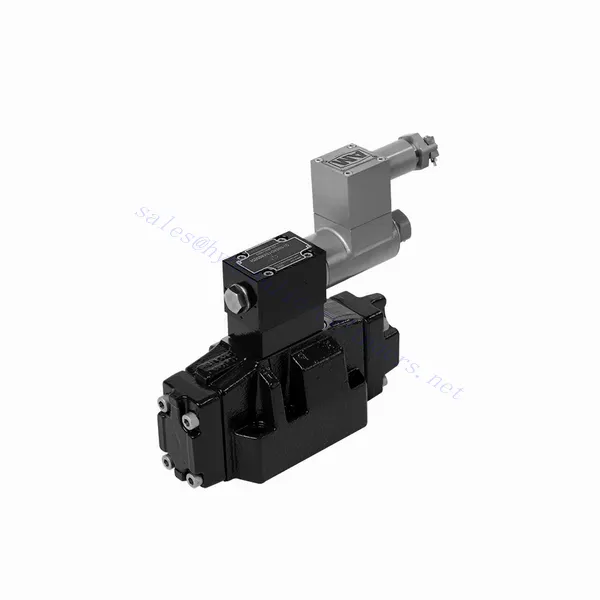
GWEH Series Explosion-proof Directional Hydraulic Valve
GWEH Series Explosion-proof Directional Hydraulic Valve
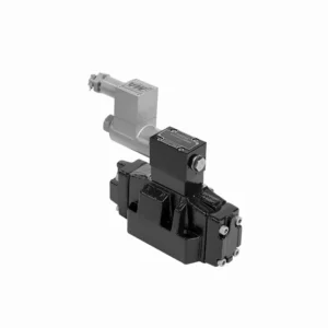
The GWEH series explosion-proof directional hydraulic valve is an innovative solution designed to provide optimal safety and precise control in hydraulic systems operating in hazardous environments. With its explosion-proof features, reliable performance, and advanced functionalities, this valve offers enhanced safety measures, efficient fluid flow control, and compatibility with various industrial applications.
The GWEH series explosion-proof directional hydraulic valve is a reliable and efficient solution for industries operating in hazardous environments. With its explosion-proof design, precise directional control, versatility, and high performance, this valve ensures safety and control in hydraulic systems. Following the recommended usage methods and adhering to regular maintenance practices, the GWEH series valve delivers safe and efficient operation in explosive atmospheres. Upgrade your hydraulic system with the GWEH series explosion-proof directional hydraulic valve and experience enhanced safety, optimal fluid flow control, and reliable performance.
GWEH Series Explosion-proof Directional Hydraulic Valve Key Characteristics:
- Dizajn odolný voči výbuchu:
- The GWEH series valve is engineered with a robust explosion-proof design, ensuring safe operation in environments containing flammable gases or dust.
- It complies with stringent safety standards and certifications, minimizing the risk of ignition and ensuring the safety of personnel and equipment.
- Smerové ovládanie:
- This hydraulic valve provides precise directional control of fluid flow, allowing for the activation and deactivation of specific hydraulic actuators.
- It enables smooth and reliable operation of various hydraulic functions, such as cylinder extension and retraction or motor direction changes.
- Versatility and Compatibility:
- The GWEH series valve is highly versatile and compatible with various hydraulic systems and applications.
- It can seamlessly integrate into industrial machinery, mobile equipment, and automation systems operating in hazardous environments.
- Vysoký výkon:
- With its advanced design and high-quality construction, the GWEH series hydraulic valve delivers exceptional performance and reliability.
- It ensures consistent and precise control over fluid flow, contributing to efficient and optimized system operation.
GWEH Series Explosion-proof Directional Hydraulic Valve Parameter:
NG10
| Working pressureP,A,B | bar | 315 | |||||||||
| Prístav T | With external pilot oil drain | bar | 315 | ||||||||
| With internal pilot oil drain | bar | 210 | |||||||||
| Prístav Y | With external pilot oil drain | bar | 210 | ||||||||
| Minimálny ovládací tlak | S externým prívodom pilotného oleja
S interným prívodom pilotného oleja (not apply to C, Z, F, G, H, P, T, V) |
bar | 3-position valve 10 | ||||||||
| Spring-return 2-position valve 10 | |||||||||||
| Hydraulic-return 2-position valve 7 | |||||||||||
| S interným prívodom pilotného oleja ( apply to C, Z, F, G, H, P, T, V) |
bar | 4.5 | |||||||||
| Max. control pressure | bar | 250 | |||||||||
| Tekutina | Minerálny olej, fosfátový ester | ||||||||||
| Rozsah teploty kvapaliny | ℃ | -30 až +80 (tesnenia NBR | |||||||||
| -20 až +80 (tesnenia FKM) | |||||||||||
| Rozsah viskozity | mm2/s | 2,8 až 500 | |||||||||
| Controlled quantity in commutating process | cm3 | 3-position valve 2.04 2-position valve 4.08 | |||||||||
| Switching times (= Valve switching time from the neutral position to the switched position)(DC ) | |||||||||||
| Control pressure | bar | 70 | 140 | 210 | 250 | ||||||
| 3-position valve | ms | 65 | 60 | 55 | 50 | ||||||
| 2-position valve | ms | 80 | 75 | 70 | 65 | ||||||
| Časy prepínania (= Čas prepínania ventilu zo zapnutej polohy do neutrálnej polohy) | |||||||||||
| 3-position valve | ms | 30 | |||||||||
| 2-position valve | ms | 35 | 40 | 30 | 35 | 25 | 30 | 20 | 25 | ||
| Flow of shortest switching time | l/min | približne 35 | |||||||||
| Montážna poloha | HC, HD, HK, HZ and HY of hydraulic return shall be installed horizontally. The rest are arbitrary | ||||||||||
NG16
| Špecifikácie | G-..WEH16../6B2.. type | |||||||
| Working pressureP,A,B bar | 350 | |||||||
| Prístav T | S externou vypúšťacou lištou pilotného oleja | 250 | ||||||
| S vnútornou vypúšťacou lištou pilotného oleja | 210 | |||||||
| Hydraulic-centering 3-position valve With internal pilot oil drain is impossible | ||||||||
| Prístav Y | S externou vypúšťacou lištou pilotného oleja | 210 | ||||||
| Minimálny ovládací tlak | With external pilot oil supply bar
With internal pilot oil supply bar |
3-position valve 14 | ||||||
| Dvojpolohový ventil s pružinovým návratom 14 | ||||||||
| Hydraulic-return 2-position valve 14 | ||||||||
| S interným prívodom pilotného oleja ( apply to C、Z、F、G、H、P、T、V) bar |
When applying back pressure valve or the flow is large, enginery of spool valve is 4.5 bar as C、Z、F、G、H、P、T and V | |||||||
| Max. ovládací tlak bar | 250 | |||||||
| Tekutina | Minerálny olej, fosfátový ester | |||||||
| Rozsah teploty kvapaliny ℃ | -30 až +80 (tesnenia NBR | |||||||
| -20 až +80 (tesnenia FKM) | ||||||||
| Viscosity range mm2 /s 2 | 2,8 až 500 | |||||||
| Objem prepínacieho pilotného oleja | ||||||||
| -Spring-centering 3-position valve cm3 | 5.72 | |||||||
| -2-position valve cm3 | 11.45 | |||||||
| * Časy prepínania (= Čas prepínania ventilu z neutrálnej polohy do prepnutej polohy) (AC a DC) | ||||||||
| Ovládací tlak bar | 50 | 150 | 250 | |||||
| – Spring-centering 3-position valve ms | 65 | 60 | 58 | |||||
| – 2-position valve ms | 65 | 55 | 50 | |||||
| *Časy prepínania (= Čas prepínania ventilu z neutrálnej polohy do prepnutej polohy) | ||||||||
| – Spring-centering 3-position valve ms | 40 | |||||||
| – 2-position valve ms | 45 | 35 | 30 | |||||
| Montážna poloha | C,D,K,Z,Y Type hydraulic-return valves are installed horizontally, the rest can be installed arbitrarily。 | |||||||
| Flow of shorter switching time L/min | približne 35 | |||||||
| Weight of the valve kg | about 10.6 | |||||||
NG25
| Špecifikácie | G-H-…WEH25../6B2… type | |||||||||
| Working pressureP,A,B bar | 350 | |||||||||
| Prístav T | S externou vypúšťacou lištou pilotného oleja | 250 | ||||||||
| S vnútornou vypúšťacou lištou pilotného oleja | 210 | |||||||||
| Hydraulic-centering 3-position valve With internal pilot oil drain is impossible | ||||||||||
| Prístav Y | S externou vypúšťacou lištou pilotného oleja | 210 | ||||||||
| Minimálny ovládací tlak | With external pilot oil supply bar
With internal pilot oil supply bar |
Spring-centering 3-position valve 13 | ||||||||
| Hydraulic-centering 3-position valve 18 | ||||||||||
| Spring-return 2-position valve 13 | ||||||||||
| Hydraulic-return 2-position valve 18 | ||||||||||
| S interným prívodom pilotného oleja | When applying back pressure valve or the flow is large, enginery of spool valve is 4.5 bar as C、Z、F、G、H、P、T and V | |||||||||
| Max. ovládací tlak bar | 250 | |||||||||
| Tekutina | Minerálny olej, fosfátový ester | |||||||||
| Rozsah teploty kvapaliny ℃ | -30 až +80 (tesnenia NBR | |||||||||
| -20 až +80 (tesnenia FKM) | ||||||||||
| Viscosity range mm2 /s 2 | 2,8 až 500 | |||||||||
| Objem prepínacieho pilotného oleja | ||||||||||
| -Spring-centering 3-position valve cm3 | 14.2 | |||||||||
| -2-position valve cm3 | 28.4 | |||||||||
| * Časy prepínania (= Čas prepínania ventilu z neutrálnej polohy do prepnutej polohy) (AC a DC) | ||||||||||
| Ovládací tlak bar | 50 | 140 | 210 | 250 | ||||||
| – Spring-centering 3-position valve ms | 85 | 75 | 70 | 65 | ||||||
| – 2-position valve ms | 160 | 130 | 120 | 105 | ||||||
| **Časy prepínania (= Čas prepínania ventilu z neutrálnej polohy do prepnutej polohy) | ||||||||||
| – Spring-centering 3-position valve ms | 40 | |||||||||
| – 2-position valve ms | 125 | 100 | 90 | 80 | ||||||
| Montážna poloha | C,D,K,Z,Y Type hydraulic-return valves are installed horizontally, the rest can be installed arbitrarily。 | |||||||||
| Flow of shorter switching time L/min | približne 35 | |||||||||
| Weight of the valve kg | about 19 | |||||||||
GWEH Series Explosion-proof Directional Hydraulic Valve Advantages:
• Directional valve directional the oil path by controlling the main spool
• Elektrohydraulické ovládanie WEH
• Two-position four-way or three-position four-way
• Installation face follows DIN 24340 A, ISO 4401, and CETOP-RP 121H Sub-plate mounting connection
• Vymeňte cievku bez úniku oleja
Usage Method Of GWEH Series Explosion-proof Directional Hydraulic Valve :
- Hazardous Area Assessment:
- Conduct a thorough assessment of the hazardous area to identify the specific explosion-proof requirements and classification.
- Determine the appropriate safety measures and precautions needed to comply with the regulations.
- Výber ventilu:
- Select the GWEH Series Valve with the suitable specifications, considering factors such as pressure ratings, flow capacity, and voltage requirements.
- Ensure compatibility with the hydraulic system and the specific hazardous environment.
- Inštalácia:
- Follow the manufacturer’s instructions for proper installation of the GWEH Series Valve in the hydraulic system.
- Ensure secure mounting and proper electrical connections, adhering to the recommended torque values and wiring guidelines.
- Control and Activation:
- Utilize the recommended control method, such as electrical signals or remote activation, to operate the GWEH Series Valve.
- Connect the valve to a suitable power source and control system, following the provided wiring diagrams.
How Does A Hydraulic Control Valve Work?
A hydraulic control valve is a critical component in hydraulic systems that regulates the flow and direction of hydraulic fluid to control the operation of hydraulic actuators. It enables precise control over various hydraulic functions, such as extending or retracting cylinders, controlling motor speed and direction, or adjusting the flow rate of hydraulic fluid. Here’s an overview of how a hydraulic control valve works:
- Štruktúra ventilu:
- A hydraulic control valve typically consists of a valve body, spools or poppets, and various internal passages.
- The valve body contains inlet and outlet ports for fluid connection and chambers that direct the flow.
- The spools or poppets are movable elements within the valve body that control the flow paths and connect the appropriate ports.
- Riadenie prietoku:
- The hydraulic control valve regulates the flow of hydraulic fluid by opening and closing specific flow paths within the valve.
- The position of the spools or poppets determines which ports are connected and allows fluid to flow in the desired direction.
- Smerové ovládanie:
- Hydraulic control valves provide directional control by selectively connecting or blocking fluid flow to different hydraulic actuators.
- By adjusting the position of the spools or poppets, the valve determines which actuator receives fluid and in which direction it moves.
- Actuation Methods:
- Hydraulic control valves can be actuated using manual levers, mechanical linkages, solenoids, or pilot pressure control.
- Manual control valves are operated by moving the levers or handles to position the spools or poppets.
- Solenoid-controlled valves use electromagnetic coils to actuate the valve, allowing for remote or automated control.
- Control Modes:
- Hydraulic control valves offer different control modes, such as 2-way, 3-way, or 4-way control.
- A 2-way control valve controls flow in one direction, allowing or blocking fluid flow.
- A 3-way control valve has three ports and can control the flow between two ports while blocking the third.
- A 4-way control valve has four ports and can route fluid between two actuator ports while blocking the other two.
- Kompenzácia tlaku:
- Some hydraulic control valves are equipped with pressure compensation features to maintain a consistent flow rate despite changes in system pressure.
- These valves adjust the flow passages based on pressure differentials, allowing for precise control regardless of varying operating conditions.
- Feedback and Control Loops:
- Advanced hydraulic control valves may incorporate feedback mechanisms, such as position or pressure sensors, to provide feedback to a control system.
- This feedback enables closed-loop control, where the system can monitor and adjust the valve’s position or flow based on desired setpoints or operating conditions.
Schopnosť a kapacita továrne:
(1) Montáž
Disponujeme prvotriednou nezávislou výskumnou a vývojovou montážnou platformou. Dielňa na výrobu hydraulických valcov má štyri poloautomatické montážne linky zdvíhacích valcov a jednu automatickú montážnu linku naklápacích valcov s projektovanou ročnou výrobnou kapacitou 1 milión kusov. Dielňa na výrobu špeciálnych valcov je vybavená rôznymi špecifikáciami poloautomatického systému čistenia a montáže s projektovanou ročnou výrobnou kapacitou 200 000 kusov a je vybavená známym CNC obrábacím zariadením, obrábacím centrom, špeciálnym zariadením na vysoko presné spracovanie valcov, robotickým zváracím strojom, automatickým čistiacim strojom, automatickým montážnym strojom valcov a automatickou lakovacou výrobnou linkou. Existujúce kritické zariadenia majú viac ako 300 súprav (sád). Optimálne alokovanie a efektívne využívanie zdrojov zariadení zabezpečuje požiadavky na presnosť výrobkov a spĺňa požiadavky na vysokú kvalitu výrobkov.


(2) Obrábanie
Obrábacia dielňa je vybavená prispôsobeným sústružníckym centrom na šikmé koľajnice, obrábacím centrom, vysokorýchlostným honovacím strojom, zváracím robotom a ďalším súvisiacim zariadením, ktoré dokáže spracovať valcové rúry s maximálnym vnútorným priemerom 400 mm a maximálnou dĺžkou 6 metrov.

(3) Zváranie

(4) Maľovanie a natieranie
S malými a stredne veľkými valcovými automatickými linkami na nanášanie farieb na vodnej báze, na dosiahnutie automatického nakladania a vykladania robotmi a automatického striekania, je projektovaná kapacita 4000 kusov za smenu;
Máme tiež poloautomatickú linku na výrobu farieb pre veľké valce poháňané reťazou s projektovanou kapacitou 60 kusov za smenu.


(5) Testovanie
Disponujeme prvotriednymi kontrolnými zariadeniami a skúšobnými zariadeniami, ktoré zabezpečujú, že výkonnosť valca spĺňa požiadavky.

Sme jedným z najlepších výrobcov hydraulických valcov. Ponúkame komplexné hydraulické valce. Poskytujeme aj zodpovedajúce poľnohospodárske prevodovkyNaše produkty sme vyvážali klientom po celom svete a vďaka vynikajúcej kvalite produktov a popredajnému servisu sme si získali dobrú reputáciu. Vítame zákazníkov doma aj v zahraničí, ktorí nás kontaktujú za účelom rokovania o obchodných záležitostiach, výmeny informácií a spolupracovať s nami!


