
Hydraulický ventil na reguláciu prietoku série Z2FRM
Ako jeden z výrobcov, dodávateľov a vývozcov mechanických výrobkov ponúkame hydraulické valce a mnoho ďalších výrobkov.
Kontaktujte nás, ak chcete získať podrobné informácie.
Pošta:sales@hydraulic-cylinders.net
Výrobca dodávateľ vývozca hydraulických valcov.
Hydraulický ventil na reguláciu prietoku série Z2FRM
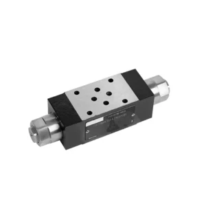
Hydraulický ventil na reguláciu prietoku série Z2FRM je najmodernejší hydraulický komponent navrhnutý tak, aby priniesol revolúciu v riadení a účinnosti hydraulických systémov. Vďaka svojim pokročilým funkciám a výnimočnému výkonu tento ventil poskytuje presnú reguláciu prietoku a zvyšuje celkovú produktivitu hydraulických strojov.
Hydraulický ventil na reguláciu prietoku série Z2FRM predstavuje prelomové riešenie pre presnú reguláciu prietoku v hydraulických systémoch. Vďaka svojej bezkonkurenčnej presnosti, všestrannosti a odolnosti umožňuje tento ventil operátorom optimalizovať výkon a účinnosť ich hydraulických strojov. Dodržiavaním odporúčaných metód používania a pokynov na údržbu môžete naplno využiť potenciál hydraulického ventilu na reguláciu prietoku série Z2FRM a zabezpečiť tak bezproblémovú prevádzku a spoľahlivú reguláciu prietoku vo vašich hydraulických aplikáciách. Modernizujte svoj hydraulický systém ešte dnes a zažite silu presného hydraulického ovládania s ventilom série Z2FRM.
Kľúčové vlastnosti hydraulického ventilu na reguláciu prietoku série Z2FRM:
- Presné riadenie prietoku:
- Ventil série Z2FRM ponúka bezkonkurenčnú presnosť pri regulácii prietoku hydraulických kvapalín, čo umožňuje jemné doladenie nastavení a optimalizovaný výkon.
- Vďaka vysokej presnosti tento ventil zaisťuje konzistentnú reguláciu prietoku, čo vedie k zvýšenej účinnosti systému a produktivite.
- Všestranné aplikácie:
- Ventil série Z2FRM je vysoko všestranný a kompatibilný so širokou škálou hydraulických systémov vrátane priemyselných strojov, stavebných zariadení a mobilných aplikácií.
- Vďaka svojej prispôsobivosti je ideálnou voľbou pre rôzne hydraulické zostavy a poskytuje spoľahlivú a efektívnu reguláciu prietoku.
- Stabilita tlaku a teploty:
- Ventil série Z2FRM je navrhnutý tak, aby odolal rôznym tlakovým a teplotným podmienkam a udržiava stabilnú reguláciu prietoku aj v náročných prevádzkových prostrediach.
- Zaisťuje konzistentný výkon, minimalizuje kolísanie prietoku a chráni integritu hydraulického systému.
- Robustná konštrukcia:
- Ventil série Z2FRM sa môže pochváliť robustnou konštrukciou a je vyrobený z vysoko kvalitných materiálov, čo zaručuje odolnosť a dlhotrvajúcu spoľahlivosť.
- Jeho robustná konštrukcia umožňuje odolávať vysokému tlaku, vibráciám a extrémnym teplotám, vďaka čomu je spoľahlivým riešením pre kritické hydraulické aplikácie.
Parameter hydraulického ventilu na reguláciu prietoku série Z2FRM:
NG6
| Regulačný ventil prietoku | |||||||||||
| Max. prevádzkový tlak - prípojka A | bar | 315 | |||||||||
| Tlakový rozdiel ΔP pre voľný spätný tok B do A | Pozri charakteristické krivky | ||||||||||
| Minimálny tlakový rozdiel | bar | 6 až 14 | |||||||||
| Tlaková stabilita až do P = 315 barov | % | ±2(Qmax) | |||||||||
| Prietok | Qmax | l/min | 0.2 | 0.6 | 1.5 | 3 | 6 | 10 | 16 | 25 | 32 |
| Qmin do 100 barov | ml/min | 15 | 15 | 15 | 15 | 25 | 50 | 70 | 100 | 250 | |
| Qmin až 315 barov | 25 | 25 | 25 | 25 | 25 | 50 | 70 | 100 | 250 | ||
| Tekutina | Minerálny olej, fosfátový ester | ||||||||||
| Rozsah teploty kvapaliny | ℃ | – 20 až + 80 | |||||||||
| Rozsah viskozity | mm2/s | 10 až 800 | |||||||||
| Stupeň kontaminácie | Maximálny povolený stupeň kontaminácie kvapaliny: Trieda 9. NAS 1638 alebo 20/18/15, ISO4406 | ||||||||||
| Montážna poloha | Voliteľné | ||||||||||
| Teplotný rozsah okolností | ℃ | -20 až +50 | |||||||||
| Hmotnosť | 2FRM6A…2FRM6B… | kg | približne 1,3 | ||||||||
| 2FRM6SB… | kg | približne 1,5 | |||||||||
| Usmerňovače | |||||||||||
| Nominálny prietok | bar | 320 | |||||||||
| Maximálny prevádzkový tlak | bar | na 210 | |||||||||
| Tlak v trhline | bar | 0.7 | |||||||||
| Hmotnosť | kg | približne 0,9 | |||||||||
NG5/10/16
| Regulačný ventil prietoku | ||||||||||||||||
| Max. prevádzkový tlak - prípojka A | bar | 315 | ||||||||||||||
| Tlakový rozdiel ΔP pre voľný spätný tok B do A | Pozri charakteristické krivky | |||||||||||||||
| Minimálny tlakový rozdiel | bar | 6 až 14 | ||||||||||||||
| Tekutina | Minerálny olej, fosfátový ester | |||||||||||||||
| Rozsah teploty kvapaliny | ℃ | – 20 až + 80 | ||||||||||||||
| Rozsah viskozity | mm2/s | 10 až 800 | ||||||||||||||
| Stupeň kontaminácie | Maximálny povolený stupeň kontaminácie kvapaliny: Trieda 9. NAS 1638 alebo 20/18/15, ISO4406 | |||||||||||||||
| Veľkosť | mm | 5 | 10 | 16 | ||||||||||||
| Max. prietok | l/min | 0.2 | 0.6 | 1.2 | 3 | 6 | 10 | 15 | 10 | 16 | 25 | 50 | 60 | 100 | 160 | |
| Spätný tok oleja B do A | ml/min | 0.5 | 0.5 | 0.6 | 0.9 | 1.8 | 3.6 | 6.7 | 2 | 2.5 | 3.5 | 6 | 2.8 | 4.3 | 7.3 | |
| Rozsah stabilného prietoku (%Qmax) (-20 – ±80 ℃) | ±5 | ±3 | ±2 | ±2 | ||||||||||||
| ±2 (P=210 barov) | ±2 (P=350 barov) | |||||||||||||||
| Pracovný tlak | bar | 210 | 350 | |||||||||||||
| Minimálny pokles tlaku | bar | 3-5 | 6-8 | 3-7 | 5-12 | |||||||||||
| Hmotnosť | kg | 1.6 | 3.4 | 7.4 | ||||||||||||
| Usmerňovače | ||||||||||||||||
| Tekutina | Minerálny olej, fosfátový ester | |||||||||||||||
| Rozsah teploty kvapaliny | -20 až +80 | |||||||||||||||
| Rozsah viskozity | 10 až 800 | |||||||||||||||
| Stupeň kontaminácie | Maximálny povolený stupeň kontaminácie kvapaliny: Trieda 9. NAS 1638 alebo 20/18/15, ISO4406 | |||||||||||||||
| Veľkosť | 5 | 10 | 16 | |||||||||||||
| Prietok | 15 | 50 | 160 | |||||||||||||
| Pracovný tlak | 210 | 315 | 315 | |||||||||||||
| Tlak v trhline | 1 | 1.5 | 1.5 | |||||||||||||
| Hmotnosť | 0.6 | 3.2 | 9.3 | |||||||||||||
Výhody hydraulického ventilu na reguláciu prietoku série Z2FRM:
• Montáž na základnú dosku pozri katalóg produktov
• Obmedzovač posunu s kompenzáciou tlaku, voliteľný
• Voliteľný jednosmerný ventil
• Gombík so stupnicou, voliteľná uzamykateľnosť
Metóda použitia hydraulického ventilu na reguláciu prietoku série Z2FRM:
- Vyhodnotenie systému:
- Začnite posúdením špecifických požiadaviek vášho hydraulického systému vrátane požadovaných prietokov, tlakových rozsahov a parametrov regulácie prietoku.
- Zistite, či je ventil série Z2FRM vhodný pre vašu aplikáciu na základe jeho možností regulácie prietoku a kompatibility s vaším systémom.
- Výber ventilu:
- Vyberte si vhodný variant ventilu série Z2FRM na základe parametrov vášho systému, požadovaného prietoku a kompatibility s ostatnými komponentmi systému.
- Zvážte faktory, ako je maximálny prietok, menovitý tlak a prevádzkové podmienky.
- Inštalácia:
- Dôsledne dodržiavajte pokyny výrobcu na inštaláciu a zabezpečte presné zarovnanie a bezpečné pripojenia ventilov.
- Venujte zvýšenú pozornosť indikátorom smeru prietoku a zabezpečte správne umiestnenie ventilu v hydraulickom systéme.
- Nastavenie regulácie prietoku:
- Po inštalácii upravte nastavenia regulácie prietoku ventilu tak, aby ste dosiahli požadovaný prietok a splnili požiadavky vášho systému.
- Jemne dolaďte ventil, aby ste optimalizovali rýchlosť a výkon hydraulických pohonov, a tým maximalizovali celkovú účinnosť systému.
Ako pridať hydraulický ventil k traktoru?
Pridanie hydraulického ventilu k traktoru môže rozšíriť jeho funkčnosť a umožniť používanie hydraulického príslušenstva a nástrojov. Tu sú všeobecné kroky, ktoré treba dodržiavať pri pridávaní hydraulického ventilu k traktoru:
- Určite hydraulický systém traktora:
- Skontrolujte, či váš traktor už má nainštalovaný hydraulický systém. Mnoho moderných traktorov je vybavených hydraulickými systémami, zatiaľ čo staršie modely môžu vyžadovať úpravy alebo dodatočné komponenty.
- Vyberte si správny hydraulický ventil:
- Vyberte si hydraulický ventil, ktorý vyhovuje vašim špecifickým potrebám a požiadavkám. Zvážte faktory, ako je prietok, menovitý tlak, počet cievok a kompatibilita s hydraulickým systémom vášho traktora.
- Zhromaždite potrebné nástroje a materiály:
- Uistite sa, že máte všetky potrebné nástroje a materiály na inštaláciu. Môže ísť o kľúče, hydraulické hadice, armatúry, montážne konzoly a samotný hydraulický ventil.
- Určte miesto inštalácie:
- Určte ideálne miesto na montáž hydraulického ventilu na vašom traktore. Zvyčajne je to v blízkosti existujúcich hydraulických portov alebo na vhodnom a dostupnom mieste.
- Pripravte si traktor:
- Pred inštaláciou vypnite motor traktora a uvoľnite akýkoľvek tlak v hydraulickom systéme pohybom hydraulických ovládacích pák tam a späť.
- Nainštalujte hydraulický ventil:
- Hydraulický ventil bezpečne namontujte pomocou vhodných konzol alebo montážneho materiálu. Uistite sa, že je správne umiestnený a zarovnaný s hydraulickými portami.
- Pripojenie hydraulických hadíc:
- Pripojte hydraulické hadice k otvorom ventilu a zabezpečte bezpečné pripojenie. Použite vhodné spojovacie prvky a správne ich utiahnite, aby ste predišli únikom.
- Pripojenie k hydraulickému systému traktora:
- Identifikujte existujúce hydraulické porty alebo spojky traktora. Pripojte hydraulické hadice z ventilu k týmto portom a zodpovedajte príslušným spojkám.
- Skúška tesnosti:
- Po vykonaní všetkých pripojení naštartujte motor traktora a ovládajte hydraulické ovládacie prvky. Starostlivo skontrolujte všetky pripojenia, či nevykazujú známky úniku hydraulickej kvapaliny. Akékoľvek netesnosti ihneď odstráňte dotiahnutím spojov alebo výmenou poškodených komponentov.
- Otestujte hydraulický ventil:
- Zapnite hydraulické ovládacie prvky a otestujte činnosť novo nainštalovaného hydraulického ventilu. Uistite sa, že funguje hladko a ovláda hydraulické príslušenstvo podľa plánu.
- Zabezpečenie a ochrana hadíc:
- Hydraulické hadice zaistite pomocou svoriek alebo konzol, aby ste predišli ich kontaktu s inými komponentmi traktora alebo ich poškodeniu počas prevádzky. Zvážte použitie ochranných krytov na hadice, aby ste ich chránili pred vplyvmi prostredia a možným oderom.
Schopnosť a kapacita továrne:
(1) Montáž
Disponujeme prvotriednou nezávislou výskumnou a vývojovou montážnou platformou. Dielňa na výrobu hydraulických valcov má štyri poloautomatické montážne linky zdvíhacích valcov a jednu automatickú montážnu linku naklápacích valcov s projektovanou ročnou výrobnou kapacitou 1 milión kusov. Dielňa na výrobu špeciálnych valcov je vybavená rôznymi špecifikáciami poloautomatického systému čistenia a montáže s projektovanou ročnou výrobnou kapacitou 200 000 kusov a je vybavená známym CNC obrábacím zariadením, obrábacím centrom, špeciálnym zariadením na vysoko presné spracovanie valcov, robotickým zváracím strojom, automatickým čistiacim strojom, automatickým montážnym strojom valcov a automatickou lakovacou výrobnou linkou. Existujúce kritické zariadenia majú viac ako 300 súprav (sád). Optimálne alokovanie a efektívne využívanie zdrojov zariadení zabezpečuje požiadavky na presnosť výrobkov a spĺňa požiadavky na vysokú kvalitu výrobkov.


(2) Obrábanie
Obrábacia dielňa je vybavená prispôsobeným sústružníckym centrom na šikmé koľajnice, obrábacím centrom, vysokorýchlostným honovacím strojom, zváracím robotom a ďalším súvisiacim zariadením, ktoré dokáže spracovať valcové rúry s maximálnym vnútorným priemerom 400 mm a maximálnou dĺžkou 6 metrov.

(3) Zváranie

(4) Maľovanie a natieranie
S malými a stredne veľkými valcovými automatickými linkami na nanášanie farieb na vodnej báze, na dosiahnutie automatického nakladania a vykladania robotmi a automatického striekania, je projektovaná kapacita 4000 kusov za smenu;
Máme tiež poloautomatickú linku na výrobu farieb pre veľké valce poháňané reťazou s projektovanou kapacitou 60 kusov za smenu.


(5) Testovanie
Disponujeme prvotriednymi kontrolnými zariadeniami a skúšobnými zariadeniami, ktoré zabezpečujú, že výkonnosť valca spĺňa požiadavky.

Sme jedným z najlepších výrobcov hydraulických valcov. Ponúkame komplexné hydraulické valce. Poskytujeme aj zodpovedajúce poľnohospodárske prevodovkyNaše produkty sme vyvážali klientom po celom svete a vďaka vynikajúcej kvalite produktov a popredajnému servisu sme si získali dobrú reputáciu. Vítame zákazníkov doma aj v zahraničí, ktorí nás kontaktujú za účelom rokovania o obchodných záležitostiach, výmeny informácií a spolupracovať s nami!
Použitie hydraulického valca:
