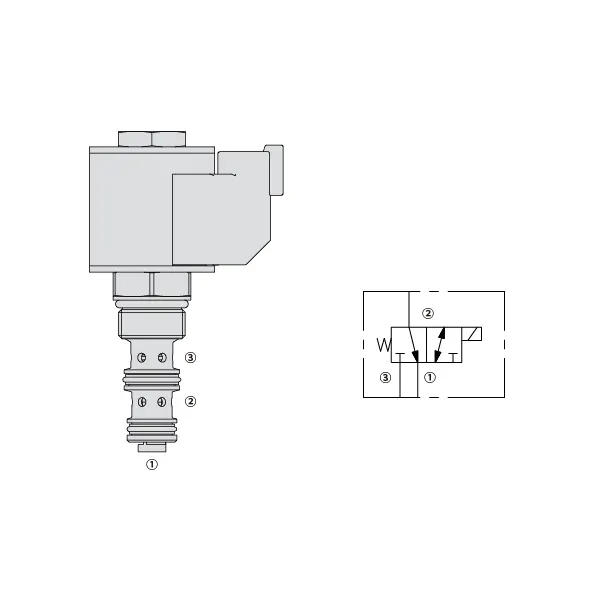
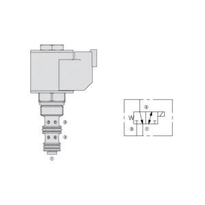
30SD08-30 Magnetni smerni ventil
30SD08-30 Magnetni smerni ventil
Experience unparalleled precision and control in your hydraulic system with the 30SD08-30 solenoid directional valve. This high-performance valve is designed to meet the demands of industrial applications, offering seamless fluid flow management and reliable operation.
The 30SD08-30 solenoid directional valve is a game-changer for hydraulic systems, offering precise control, high flow capacity, and rapid response time. With its durability and reliability, this valve guarantees optimal performance and efficiency. By following the recommended usage methods and maintenance guidelines, you can harness the full potential of the 30SD08-30 solenoid directional valve, achieving seamless control, increased productivity, and improved overall performance. Upgrade your hydraulic system today with the 30SD08-30 solenoid directional valve and experience the precision and reliability it brings to your operations.
30SD08-26 Solenoid Directional Valve Characteristics:
- Accurate Fluid Flow Control:
- The 30SD08-30 solenoid directional valve provides precise control over fluid flow, ensuring accurate and reliable operation of your hydraulic system.
- Experience seamless adjustments in flow rates, facilitating optimal performance in various industrial applications.
- Visoka pretočnost:
- With its high flow capacity design, the 30SD08-30 solenoid directional valve can handle substantial fluid volumes efficiently.
- This feature enables smooth and reliable operation, even in applications that require high flow rates, ensuring optimal system performance.
- Hiter odzivni čas:
- Equipped with advanced solenoid technology, the 30SD08-30 solenoid directional valve boasts a rapid response time.
- Experience swift and accurate adjustments in fluid flow direction, allowing for enhanced system efficiency and precise control.
- Durability and Reliability:
- Built to withstand demanding operating conditions, the 30SD08-30 solenoid directional valve features a robust construction.
- Its durable materials and reliable design minimize downtime, reduce maintenance requirements, and ensure long-lasting performance.
Parameter elektromagnetnega smernega ventila 30SD08-25:
| Nazivni tlak | 207 barov (3000 psi) |
| Najvišji pretok | Glejte tabelo uspešnosti |
| Tekočina | Mineralna ali sintetična olja z mazalnimi lastnostmi |
| Temperaturno območje tekočine ℃ | -54 do 107 ℃ (poliuretanska tesnila) |
| -40 do 100 ℃ (tesnila Buna N) | |
| -26 do 204 ℃ (tesnila iz fluoroogljika) | |
| Območje viskoznosti | 7,4 do 420 mm2/s |
| Stopnja kontaminacije | Najnižja stopnja onesnaženosti je po standardu ISO4406 20/18/14, za podaljšanje življenjske dobe pa je priporočljiva stopnja 17/15/13. |
| Notranje puščanje | Port 3 (De-energized): ≤ 82 mL/min@207bar |
| Port 1 (Energized): ≤ 164 mL/min@207bar | |
| Votlina | VC08-3(Cavity variation ‘A’, see technical reference) |
| Nazivna obremenitev tuljave | Neprekinjeno od 85% do 115% nazivne napetosti |
| Začetni tok tuljave pri 20 ℃ | 1,4 A pri 12 V enosmernem toku; 0,7 A pri 24 V enosmernem toku |
| Minimalna vklopna napetost | 85% nominalnega tlaka pri 207 barih (3000 psi) |
Prednosti elektromagnetnega smernega ventila 30SD08-25:
• Tuljava za neprekinjeno delovanje
• Učinkovita konstrukcija z mokro armaturo
• Kartuše so zamenljive glede na napetost
• Izbirne vodoodporne e-tuljave z zaščito do IP69K
• Kaljeni deli za dolgo življenjsko dobo
Način uporabe elektromagnetnega smernega ventila 30SD08-25:
- Vrednotenje sistema:
- Begin by assessing the specific requirements of your hydraulic system, considering flow rates, pressure levels, and system dynamics.
- Evaluate if the 30SD08-30 Solenoid Directional Valve aligns with your system’s needs, taking into account its precision, flow capacity, and compatibility with other components.
- Izbira ventila:
- Select the appropriate variant of the 30SD08-30 solenoid directional valve based on your system parameters and performance requirements.
- Consider factors such as flow capacity, pressure ratings, and compatibility to ensure seamless integration and optimal functionality.
- Namestitev:
- Follow the manufacturer’s installation instructions carefully to ensure proper placement and secure mounting of the valve.
- Ventil pravilno namestite v hidravlični sistem, pri čemer upoštevajte smer pretoka tekočine in dostopnost za namene vzdrževanja.
- Električne povezave:
- Priključite elektromagnetni ventil na predvideni vir napajanja v skladu s specifikacijami proizvajalca.
- Ensure that the electrical connections are secure, adhering to safety standards and guidelines.
Kako priključiti hidravlični ventil za regulacijo pretoka?
Za priključitev hidravličnega ventila za regulacijo pretoka sledite tem korakom:
- Določite vrsto ventila: Določite specifično vrsto ventila za regulacijo pretoka, s katerim delate. Med pogoste vrste spadajo iglični ventili, nastavljivi ventili za regulacijo pretoka ali ventili za regulacijo pretoka s kompenzacijo tlaka. Prepričajte se, da je ventil primeren za vašo uporabo in združljiv z vašim hidravličnim sistemom.
- Zberite potrebna orodja in materiale: Zberite potrebno orodje in materiale, vključno z ustreznimi hidravličnimi priključki, adapterji, cevmi in ključi.
- Priprava hidravličnega sistema: Zaustavite hidravlični sistem in sprostite morebitni tlak v sistemu z aktiviranjem varnostnega ventila ali umikanjem hidravličnih cilindrov. Ta korak je ključnega pomena za varnost.
- Določite smer pretoka: Določite smer pretoka v vašem hidravličnem sistemu. Smer pretoka je običajno označena s puščicami na hidravličnih komponentah. Preden nadaljujete, se prepričajte, da razumete pravilno smer pretoka.
- Poiščite mesto namestitve: Določite optimalno mesto za namestitev ventila za regulacijo pretoka v vašem hidravličnem sistemu. Upoštevajte dejavnike, kot so dostopnost, bližina aktuatorja ali hidravlične komponente in enostavnost nastavitve.
- Namestitev ventila: Varno namestite ventil za regulacijo pretoka na izbrano mesto z ustreznimi nosilci ali sponkami. Prepričajte se, da je ventil pravilno nameščen, tako da sta vhodna in izhodna odprtina poravnana s smerjo pretoka.
- Priključite vhodne in izhodne odprtine: Hidravlične cevi ali cevje pritrdite na vhodne in izhodne odprtine ventila za regulacijo pretoka. Za vzpostavitev netesne povezave uporabite ustrezne hidravlične spojke in adapterje. Priključke privijte s ključi, da zagotovite varno prileganje, vendar jih ne zategujte premočno.
- Prilagodite nadzor pretoka: Glede na vrsto ventila za regulacijo pretoka ima lahko nastavljive funkcije, kot sta igelni ventil ali gumb za regulacijo pretoka. Ventil prilagodite želenemu pretoku ali hitrosti. Za specifične postopke nastavitve glejte navodila proizvajalca.
- Preizkusite sistem: Ko je ventil za regulacijo pretoka nameščen in nastavljen, počasi obnovite tlak v hidravličnem sistemu. Preizkusite sistem, da se prepričate, da ventil za regulacijo pretoka deluje pravilno. Spremljajte pretok ali hitrost hidravličnega aktuatorja, da preverite, ali je znotraj želenega območja.
- Natančna nastavitev in spremljanje: Prilagodite ventil za regulacijo pretoka, da dosežete želeni pretok ali hitrost. Redno spremljajte hidravlični sistem glede puščanja, neskladij tlaka ali nenavadnega delovanja.
Zmogljivost in zmogljivost tovarne:
(1) Sestavljanje
Imamo prvovrstno neodvisno platformo za raziskave in razvoj. Delavnica za proizvodnjo hidravličnih cilindrov ima štiri polavtomatske montažne linije za dvižne cilindre in eno avtomatsko montažno linijo za nagibne cilindre z letno proizvodno zmogljivostjo 1 milijona kosov. Delavnica za posebne cilindre je opremljena z različnimi specifikacijami polavtomatskega sistema za čiščenje in montažo z letno proizvodno zmogljivostjo 200.000 kosov ter znano CNC obdelovalno opremo, obdelovalnim centrom, visoko precizno posebno opremo za obdelavo cilindrov, robotskim varilnim strojem, avtomatskim čistilnim strojem, avtomatskim strojem za montažo cilindrov in avtomatsko proizvodno linijo za barvanje. Obstoječa kritična oprema obsega več kot 300 kompletov (kompletov). Optimalna razporeditev in učinkovita uporaba opremnih virov zagotavljata zahteve glede natančnosti izdelkov in izpolnjujeta visoke zahteve glede kakovosti izdelkov.


(2) Strojna obdelava
Strojna delavnica je opremljena s prilagojenim centrom za struženje nagnjenih tirnic, obdelovalnim centrom, visokohitrostnim strojem za honanje, varilnim robotom in drugo sorodno opremo, ki lahko obdeluje cilindrične cevi z največjim notranjim premerom 400 mm in največjo dolžino 6 metrov.

(3) Varjenje

(4) Barvanje in premazovanje
Z majhnimi in srednje velikimi cilindričnimi avtomatskimi linijami za barvanje na vodni osnovi, za doseganje avtomatskega nakladanja in razkladanja robotov ter avtomatskega brizganja, je projektna zmogljivost 4000 kosov na izmeno;
Imamo tudi polavtomatsko linijo za proizvodnjo barv za velike jeklenke, ki jo poganja veriga, s projektno zmogljivostjo 60 zabojev na izmeno.


(5) Testiranje
Imamo prvovrstne inšpekcijske prostore in testne postaje, s katerimi zagotavljamo, da delovanje jeklenke izpolnjuje zahteve.

Smo eden najboljših proizvajalcev hidravličnih cilindrov. Ponujamo vam celovite hidravlične cilindre. Zagotavljamo tudi ustrezne kmetijski menjalnikiNaše izdelke smo izvozili strankam po vsem svetu in si prislužili dober ugled zaradi vrhunske kakovosti izdelkov in poprodajnih storitev. Z veseljem vas vabimo, da nas kontaktirate za poslovne dogovore, izmenjavo informacij in ... sodelujte z nami!