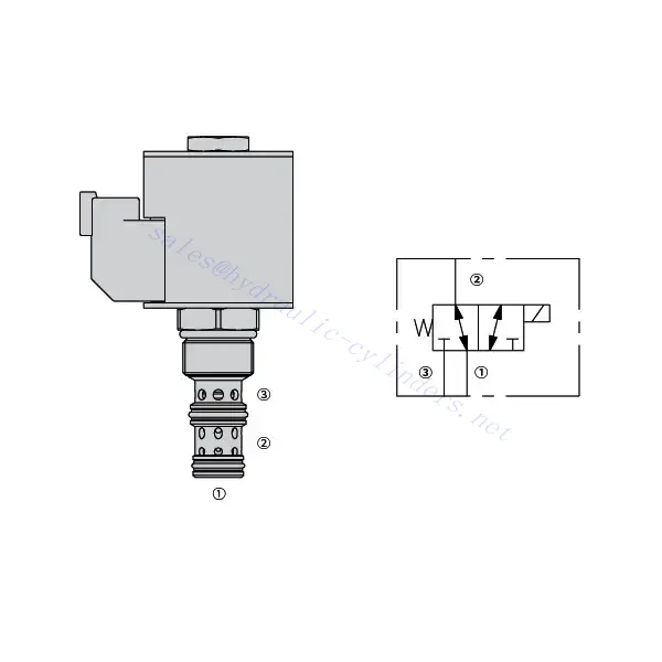
30SD10-34 Solenoid Directional Valve
Kot eden od proizvajalcev, dobaviteljev in izvoznikov hidravličnih cilindrov ponujamo hidravlične cilindre in številne druge izdelke.
Za podrobnosti se obrnite na nas.
Pošta:sales@hydraulic-cylinders.net
Proizvajalec, dobavitelj in izvoznik hidravličnih cilindrov.
30SD10-34 Solenoid Directional Valve
The 30SD10-34 solenoid directional valve is a cutting-edge industrial component designed to provide precise and reliable fluid control in a wide range of applications. With its advanced features, durable construction, and user-friendly design, this solenoid directional valve offers enhanced performance and efficiency.
The 30SD10-34 solenoid directional valve is a reliable and versatile component that offers precise fluid control in industrial applications. Its robust construction, precision control, and reliable performance make it an ideal choice for enhancing the efficiency and productivity of your fluid control systems. By following the recommended usage methods and maintenance guidelines, you can ensure optimal performance and longevity of the 30SD10-34 solenoid directional valve in your industrial operations.
30SD10-34 Solenoid Directional Valve Characteristics:
- Robust Construction: The 30SD10-34 solenoid directional valve is built with high-quality materials and meticulous craftsmanship, ensuring durability and longevity. Its robust construction allows it to withstand demanding industrial environments, providing reliable performance even under harsh conditions.
- Versatile Functionality: This solenoid directional valve offers versatile functionality, making it suitable for various applications. It effectively controls the direction of fluid flow, allowing precise and efficient operation in different industrial systems.
- Precision Control: With exceptional precision, the 30SD10-34 solenoid directional valve enables accurate control over fluid flow. It allows for precise regulation and adjustment of fluid direction and pressure, ensuring optimal performance and efficiency in industrial processes.
- Reliable Performance: This solenoid directional valve delivers reliable performance, minimizing the risk of system failures or interruptions. It operates dependably, contributing to increased productivity and reduced downtime in industrial operations.
30SD10-34 Solenoid Directional Valve Parameter:
| Nazivni tlak | 207 barov (3000 psi) | |
| Proof pressure | 350 bar (5075 psi) | |
| Najvišji pretok | 22.7 L/min (6 gpm) | |
| Tekočina | Mineralna ali sintetična olja z mazalnimi lastnostmi | |
| Temperature range ℃ | -54 do 107 ℃ (poliuretanska tesnila) | |
| -40 do 100 ℃ (tesnila Buna N) | ||
| -26 do 204 ℃ (tesnila iz fluoroogljika) | ||
| Območje viskoznosti | 7,4 do 420 mm2/s | |
| Stopnja kontaminacije | Najnižja stopnja onesnaženosti je po standardu ISO4406 20/18/14, za podaljšanje življenjske dobe pa je priporočljiva stopnja 17/15/13. | |
| Notranje puščanje | ≤ 115 mL/min@207bar | |
| Votlina | VC10-3 | |
| Nazivna obremenitev tuljave | Neprekinjeno od 85% do 115% nazivne napetosti | |
| Response time | First indication of change of state with 100% voltage supplied at80% of nominal flow rating:Energized: 60 msec. ; De-energized: 10 msec. | |
| Začetni tok tuljave pri 20 ℃ | E-tuljava | 1,7 A pri 12 V enosmernem toku; 0,85 A pri 24 V enosmernem toku |
| D-tuljava | 1,67 A pri 12 V enosmernem toku; 0,83 A pri 24 V enosmernem toku | |
| Minimalna vklopna napetost | 85% of nominal at 207 bar | |
30SD10-34 Solenoid Directional Valve Advantages:
• Tuljava za neprekinjeno delovanje
• Učinkovita konstrukcija z mokro armaturo
• Kartuše so zamenljive glede na napetost
• Izbirne vodoodporne e-tuljave z zaščito do IP69K
• All ports may be fully pressurized
• Industrijska običajna votlina
• Kaljeni deli za dolgo življenjsko dobo in nizko puščanje
Usage Method Of 30SD10-34 Solenoid Directional Valve:
- Integration into System: Integrate the 30SD10-34 solenoid directional valve into the fluid control system following the manufacturer’s guidelines and specifications. Ensure proper alignment and connection between the valve and other system components to achieve optimal performance.
- Electrical Connection: Establish a secure electrical connection for the solenoid directional valve. Refer to the provided wiring diagram and ensure correct polarity to prevent any electrical malfunctions. Follow safety guidelines when working with electrical connections.
- Nadzor smeri pretoka tekočine: Za nadzor smeri pretoka tekočine uporabite elektromagnetni smerni ventil. Ventil je običajno opremljen z ročico ali aktuatorjem za ročno nastavitev. Lahko pa ga integrirate v avtomatiziran krmilni sistem za daljinsko upravljanje.
- Pressure Adjustment: Employ the solenoid directional valve to regulate fluid pressure within the system. By adjusting the valve’s settings, you can achieve the desired pressure levels for optimal performance and efficiency.
How To Plumb Auto Cycle Hydraulic Valve?
Plumbing an auto-cycle hydraulic valve requires careful attention to ensure proper installation and functionality. Follow these steps to plumb an auto-cycle hydraulic valve effectively:
- Zberite potrebna orodja in materiale: Before you begin, make sure you have all the required tools and materials, including hydraulic hoses, fittings, adapters, Teflon tape, wrenches, and a hydraulic fluid reservoir.
- Identify The Valve Ports: Examine the auto-cycle hydraulic valve to identify the different ports. Typically, there will be inlet ports, outlet ports, and possibly additional ports for pressure relief or auxiliary functions.
- Determine The Hydraulic Fluid Flow Direction: Determine the desired flow direction of the hydraulic fluid through the valve. This information is crucial for correctly connecting the inlet and outlet ports.
- Install Fittings And Adapters: Install the appropriate fittings and adapters onto the valve ports. Ensure they are tightened securely, but be careful not to overtighten and damage the threads.
- Apply Teflon Tape: Wrap Teflon tape around the threads of the fittings and adapters. This helps create a tight seal and prevents leaks.
- Connect Hydraulic Hoses: Attach hydraulic hoses to the fittings and adapters on the valve ports. Ensure the hoses are suitable for the hydraulic system’s pressure rating and are of the correct length.
- Secure Hose Connections: Use hose clamps or other suitable methods to secure the hydraulic hoses to the fittings. This prevents the hoses from coming loose during operation.
- Route The Hydraulic hoses: Carefully route the hydraulic hoses to connect the auto-cycle hydraulic valve to the hydraulic fluid reservoir and other hydraulic components, such as cylinders or motors. Avoid sharp bends or kinks in the hoses that could restrict fluid flow.
- Check For Leaks: Once all connections are made, check for leaks. Start by slowly pressurizing the system and inspecting each connection point. If you notice any leaks, tighten the fittings or replace faulty components as necessary.
- Fill The Hydraulic Fluid Reservoir: Fill the hydraulic fluid reservoir with the recommended type and quantity of hydraulic fluid. Refer to the manufacturer’s guidelines for the appropriate fluid specifications.
- Bleed Air From The System: B bleed any air trapped in the hydraulic system to ensure proper operation. Follow the manufacturer’s instructions for bleeding procedures, which typically involve cycling the design and opening bleed valves.
- Test The System: With the plumbing complete, test the auto-cycle hydraulic valve and the overall system’s performance. Verify that the valve functions as intended and that fluid flow is smooth and consistent.
Zmogljivost in zmogljivost tovarne:
(1) Sestavljanje
Imamo prvovrstno neodvisno platformo za raziskave in razvoj. Delavnica za proizvodnjo hidravličnih cilindrov ima štiri polavtomatske montažne linije za dvižne cilindre in eno avtomatsko montažno linijo za nagibne cilindre z letno proizvodno zmogljivostjo 1 milijona kosov. Delavnica za posebne cilindre je opremljena z različnimi specifikacijami polavtomatskega sistema za čiščenje in montažo z letno proizvodno zmogljivostjo 200.000 kosov ter znano CNC obdelovalno opremo, obdelovalnim centrom, visoko precizno posebno opremo za obdelavo cilindrov, robotskim varilnim strojem, avtomatskim čistilnim strojem, avtomatskim strojem za montažo cilindrov in avtomatsko proizvodno linijo za barvanje. Obstoječa kritična oprema obsega več kot 300 kompletov (kompletov). Optimalna razporeditev in učinkovita uporaba opremnih virov zagotavljata zahteve glede natančnosti izdelkov in izpolnjujeta visoke zahteve glede kakovosti izdelkov.


(2) Strojna obdelava
Strojna delavnica je opremljena s prilagojenim centrom za struženje nagnjenih tirnic, obdelovalnim centrom, visokohitrostnim strojem za honanje, varilnim robotom in drugo sorodno opremo, ki lahko obdeluje cilindrične cevi z največjim notranjim premerom 400 mm in največjo dolžino 6 metrov.

(3) Varjenje

(4) Barvanje in premazovanje
Z majhnimi in srednje velikimi cilindričnimi avtomatskimi linijami za barvanje na vodni osnovi, za doseganje avtomatskega nakladanja in razkladanja robotov ter avtomatskega brizganja, je projektna zmogljivost 4000 kosov na izmeno;
Imamo tudi polavtomatsko linijo za proizvodnjo barv za velike jeklenke, ki jo poganja veriga, s projektno zmogljivostjo 60 zabojev na izmeno.


(5) Testiranje
Imamo prvovrstne inšpekcijske prostore in testne postaje, s katerimi zagotavljamo, da delovanje jeklenke izpolnjuje zahteve.

Smo eden najboljših proizvajalcev hidravličnih cilindrov. Ponujamo vam celovite hidravlične cilindre. Zagotavljamo tudi ustrezne kmetijski menjalnikiNaše izdelke smo izvozili strankam po vsem svetu in si prislužili dober ugled zaradi vrhunske kakovosti izdelkov in poprodajnih storitev. Z veseljem vas vabimo, da nas kontaktirate za poslovne dogovore, izmenjavo informacij in ... sodelujte z nami!
Uporaba hidravličnega cilindra:
