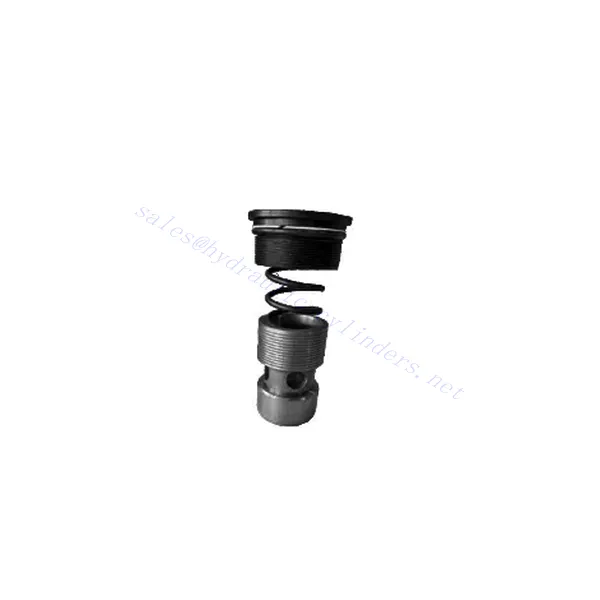
M-SR Series Check Hydraulic Valve Cartridge
M-SR Series Check Hydraulic Valve Cartridge
The M-SR series check hydraulic valve cartridge is versatile and essential in hydraulic systems. This valve cartridge is designed to regulate fluid flow and prevent backflow and offers reliable performance, durability, and ease of installation.
The M-SR series check hydraulic valve cartridge is a reliable and efficient solution for fluid control in hydraulic systems. With efficient check valve functionality, compact design, high flow capacity, and robust construction, this valve cartridge ensures optimal system performance, prevents backflow, and enhances overall efficiency. By following the recommended usage methods and maintenance practices, the M-SR series check hydraulic valve cartridge delivers reliable operation and extends the lifespan of hydraulic systems. Upgrade your hydraulic system with the m-sr series check hydraulic valve cartridge and experience efficient and reliable fluid control.
M-SR Series Check Hydraulic Valve Cartridge Key Characteristics:
- Effektiv backventilfunktionalitet:
- The M-SR series valve cartridge features a built-in check valve mechanism that enables the unidirectional flow of hydraulic fluid.
- It effectively prevents backflow and ensures fluid flows in the desired direction, minimizing the risk of system damage and inefficiency.
- Kompakt och mångsidig design:
- The valve cartridge is compact, making it suitable for applications with limited space or where weight considerations are crucial.
- Its versatile design allows easy integration into various hydraulic systems, including mobile machinery, industrial equipment, and hydraulic power units.
- Hög flödeskapacitet:
- Despite its compact size, the M-SR series valve cartridge offers high flow capacity, allowing for efficient fluid transfer and system performance.
- It minimizes pressure drops, ensuring optimal hydraulic power delivery to actuators and other components.
- Robust konstruktion:
- Constructed from high-quality materials, the M-SR series valve cartridge demonstrates excellent durability and resistance to wear and corrosion.
- It is designed to withstand demanding operating conditions, prolonging the valve cartridge’s lifespan and reducing maintenance requirements.
M-SR Series Check Hydraulic Valve Cartridge Parameter:
| Specifikationer | bar | NG6-30 | |||||
| Max. driftstryck | bar | 315 | |||||
| Spricktryck | bar | Refer to the characteristic curve | |||||
| Max. flödeshastighet | l/min | Refer to the characteristic curve | |||||
| Viskositetsområde | mm2/s | 2,8 till 380 | |||||
| Vätsketemperaturområde | ℃ | -30 to +80(NBR seals) | |||||
| -20 to +80(FKM seals) | |||||||
| Vätska | Mineralolja lämplig för NBR- och FKM-tätningar | ||||||
| Fosfatester för FKM-tätning | |||||||
| Grad av kontaminering | Maximal tillåten grad av vätskeförorening: Klass 9. NAS 1638 eller 20/18/15, ISO4406 | ||||||
| Storlek | 8 | 10 | 15 | 20 | 25 | 30 | |
| Weight: Right angled check valve cartridge | kg | 0.03 | 0.05 | 0.08 | 0.14 | 0.32 | 0.47 |
M-SR Series Check Hydraulic Valve Cartridge Advantages:
NG6-30
• Används vid installation av oljevägsblock
• Leak-free closure
• Various opening pressures available (see model description)
Usage Method Of M-SR Series Check Hydraulic Valve Cartridge:
- Systemanalys:
- Before installation, thoroughly analyze the hydraulic system to determine the specific requirements and operational parameters.
- Consider factors such as flow rates, pressure ratings, and compatibility with the M-SR series valve cartridge.
- Ventilval:
- Select the appropriate M-SR series valve cartridge variant based on the system requirements and specifications.
- Tänk på faktorer som flödeskapacitet, tryckklassningar och kompatibilitet med andra systemkomponenter.
- Installation:
- Follow the manufacturer’s instructions for properly installing the M-SR series valve cartridge in the hydraulic system.
- Ensure a secure fit within the valve cavity, proper alignment with the fluid flow path, and appropriate sealing to prevent leaks.
- Vätskeflödesriktning:
- Ensure the M-SR Series Valve Cartridge is installed in the correct orientation, allowing for the desired fluid flow direction.
- Rikta in ventilpatronen med systemets flödesväg och säkerställ att backventilens mekanism är korrekt aktiverad.
How Does A Hydraulic Diverter Valve Work?
A hydraulic diverter valve is a key component in hydraulic systems that allows the operator to redirect hydraulic fluid flow from one path to another. It provides flexibility in controlling the flow direction and enables the use of multiple hydraulic actuators with a single hydraulic power source. Here’s a breakdown of how a hydraulic diverter valve works:
- Ventilstruktur:
- A hydraulic diverter valve typically consists of a valve body with multiple ports, a movable spool or ball, and actuators such as levers, solenoids, or pilot pressure mechanisms.
- The valve body contains internal passages and chambers that direct the flow of hydraulic fluid.
- Vätskeflödesvägar:
- The diverter valve has multiple ports that connect to different hydraulic components in the system, such as the pump, reservoir, actuators, and other valves.
- These ports include an inlet port, outlet ports, and work ports, each serving a specific purpose in controlling the fluid flow.
- Spool or Ball:
- The valve body houses a movable spool or ball that controls the flow of hydraulic fluid.
- The spool can slide within the valve body, while the ball can rotate or move linearly to open or close specific passages.
- Actuation Mechanisms:
- Hydraulic diverter valves can be actuated manually, electrically, or hydraulically, depending on the specific design and application requirement.
- Manual actuation involves levers or handles that the operator physically moves to position the spool or ball.
- Electrical actuation utilizes solenoids that receive electrical signals to shift the spool or ball, allowing for remote control and automation.
- Hydraulic actuation employs pilot pressure to move the spool or ball, often in conjunction with electrical or manual control.
- Ventilpositioner:
- Depending on the valve design, there are typically multiple positions that the spool or ball can assume, each corresponding to a specific flow path.
- Common positions include neutral, where all ports are blocked, and various actuating positions that allow flow between specific ports.
- As the spool or ball shifts, it aligns with specific ports, opening or closing passages and directing the hydraulic fluid accordingly.
- Operator Input:
- The operator engages the hydraulic diverter valve by actuating the manual lever, applying electrical signals to solenoids, or manipulating pilot pressure.
- This input determines the desired valve position, which in turn determines the flow direction and the action of the hydraulic actuators.
- System Operation:
- Once the hydraulic diverter valve is in the desired position, hydraulic fluid flows through the appropriate passages and ports.
- This flow of fluid can be directed to different hydraulic actuators, allowing for selective control of the actuator’s movement or operation.
Fabrikens kapacitet och kapacitet:
(1) Montering
Vi har en förstklassig oberoende forsknings- och utvecklingsplattform. Verkstaden för tillverkning av hydraulcylindrar har fyra halvautomatiska monteringslinjer för lyftcylindrar och en automatisk monteringslinje för tiltcylindrar, med en planerad årlig produktionskapacitet på 1 miljon enheter. Specialcylinderverkstaden är utrustad med olika specifikationer för ett halvautomatiskt rengöringsmonteringssystem med en planerad årlig produktionskapacitet på 200 000 och utrustad med känd CNC-bearbetningsutrustning, ett fleroperationscenter, en specialutrustning för högprecisionscylindrar, en robotsvetsmaskin, en automatisk rengöringsmaskin, en automatisk cylindermonteringsmaskin och en automatisk produktionslinje för målning. Befintlig kritisk utrustning på mer än 300 set (set). Optimal allokering och effektiv användning av utrustningsresurser säkerställer produkternas noggrannhetskrav och uppfyller produkternas höga kvalitetsbehov.


(2) Maskinbearbetning
Bearbetningsverkstaden är utrustad med en specialanpassad svarvcentral för lutande räls, bearbetningscenter, höghastighetshönsmaskin, svetsrobot och annan relaterad utrustning, som kan hantera bearbetning av cylinderrör med en maximal innerdiameter på 400 mm och en maximal längd på 6 meter.

(3) Svetsning

(4) Målning och ytbehandling
Med små och medelstora cylindriska automatiska vattenbaserade färgbeläggningslinjer, för att uppnå automatisk robotlastning och lossning samt automatisk sprutning, är den designade kapaciteten 4000 stycken per skift;
Vi har även en halvautomatisk färgproduktionslinje för stora cylindrar som drivs av en släpkedja, med en designkapacitet på 60 lådor per skift.


(5) Testning
Vi har förstklassiga inspektionsanläggningar och testbäddar för att säkerställa att cylinderns prestanda uppfyller kraven.

Vi är en av de bästa tillverkarna av hydraulcylindrar. Vi kan erbjuda ett heltäckande utbud av hydraulcylindrar. Vi tillhandahåller även motsvarande jordbruksväxellådorVi har exporterat våra produkter till kunder över hela världen och fått ett gott rykte tack vare vår överlägsna produktkvalitet och kundservice. Vi välkomnar kunder både hemma och utomlands att kontakta oss för att förhandla affärer, utbyta information och samarbeta med oss!


