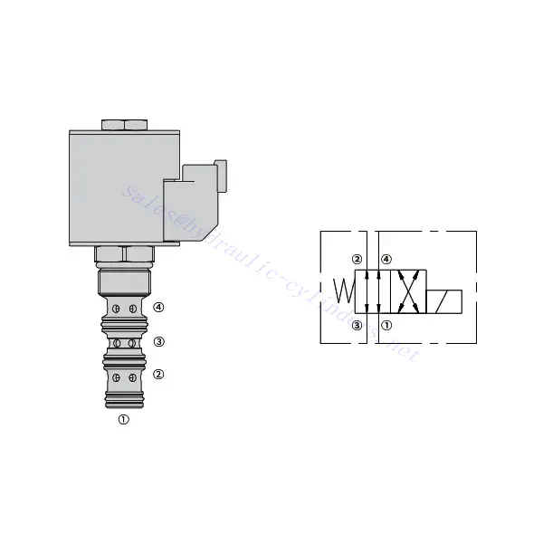
30SD10-40 Magnetriktningsventil
Som en av tillverkarna, leverantörerna och exportörerna av mekaniska produkter erbjuder vi hydraulcylindrar och många andra produkter.
Vänligen kontakta oss för mer information.
E-post:sales@hydraulic-cylinders.net
Tillverkare, leverantör och exportör av hydraulcylindrar.
30SD10-40 Magnetriktningsventil
Magnetriktningsventilen 30SD10-40 är en högpresterande industriell komponent som är utformad för att ge exakt och tillförlitlig vätskekontroll i en mängd olika tillämpningar. Med sina avancerade funktioner, hållbara konstruktion och användarvänliga design erbjuder denna magnetriktningsventil förbättrad effektivitet och driftsäkerhet.
Magnetriktningsventilen 30SD10-40 är en pålitlig och mångsidig komponent som erbjuder exakt vätskekontroll i industriella applikationer. Dess robusta konstruktion, precisionskontroll och tillförlitliga prestanda förbättrar effektiviteten och produktiviteten i vätskekontrollsystem. Genom att följa de rekommenderade användningsmetoderna och underhållsriktlinjerna kan du säkerställa optimal prestanda och livslängd för magnetriktningsventilen 30SD10-40 i din industriella verksamhet.
Egenskaper för 30SD10-40 magnetriktningsventil:
- Robust konstruktion: Magnetventilen 30SD10-40 är tillverkad med exceptionellt hantverk och högkvalitativa material, vilket garanterar hållbarhet och lång livslängd. Dess robusta konstruktion gör att den klarar krävande industriella miljöer och ger pålitlig prestanda även under tuffa förhållanden.
- Mångsidig funktionalitet: Denna magnetiska riktningsventil erbjuder mångsidig funktionalitet, vilket gör den lämplig för en mängd olika tillämpningar. Den styr effektivt vätskeflödets riktning, vilket möjliggör exakt och effektiv drift i olika industriella system.
- Precisionsstyrning: Magnetriktningsventilen 30SD10-40 ger exceptionell precision vid vätskestyrning. Den möjliggör noggrann reglering och justering av vätskeriktning och tryck, vilket säkerställer optimal prestanda och effektivitet i industriella processer.
- Tillförlitlig prestanda: Denna magnetiska riktningsventil ger tillförlitlig prestanda och minimerar risken för systemfel eller avbrott. Den arbetar med tillförlitlighet, vilket bidrar till ökad produktivitet och minskad stilleståndstid i industriell verksamhet.
Parameter för 30SD10-40 magnetriktningsventil:
| Nominellt tryck | 207 bar (3000 psi) | |
| Toppflöde | 23 l/min (6 gpm) | |
| Vätska | Mineralbaserade eller syntetiska med smörjande egenskaper | |
| Temperaturområde ℃ | -54 till 107 ℃ (polyuretantätningar) | |
| -40 till 100 ℃ (Buna N-tätningar) | ||
| -26 till 204 ℃ (Fluorkarbontätningar) | ||
| Viskositetsområde | 7,4 till 420 mm2/s | |
| Grad av kontaminering | Lägsta föroreningsnivå är ISO4406 nivå 20/18/14, och nivå 17/15/13 rekommenderas för att förlänga livslängden. | |
| Internt läckage | ≤ 82 ml/min vid 207 bar | |
| Hålighet | VC10-4 | |
| Spolbelastningsklassning | Kontinuerlig från 85% till 115% nominell spänning | |
| Initial spolströmsförbrukning vid 20 ℃ | E-spole | 1,7A vid 12VDC; 0,85A vid 24VDC |
| D-spole | 1,67 A vid 12 VDC; 0,83 A vid 24 VDC | |
| Minsta inspänning | 85% av nominellt tryck vid 207 bar | |
Fördelar med 30SD10-40 magnetriktningsventil:
• Spole för kontinuerlig drift
• Patroner är utbytbara mellan spänningar
• Vattentäta e-spolar som tillval, klassade upp till IP69K
• Effektiv våtarmaturkonstruktion
• Industrigemensamt hålrum
• Härdade delar för lång livslängd
Användningsmetod för 30SD10-40 magnetriktningsventil :
- Integrering i systemet: Integrera magnetventilen 30SD10-40 i vätskekontrollsystemet enligt tillverkarens riktlinjer och specifikationer. Säkerställ korrekt inriktning och anslutning mellan ventilen och andra systemkomponenter för att uppnå optimal prestanda.
- Elanslutning: Upprätta en säker elektrisk anslutning för magnetventilen. Följ det medföljande kopplingsschemat och säkerställ korrekt polaritet för att förhindra elektriska fel. Följ säkerhetsföreskrifterna vid arbete med elektriska anslutningar.
- Styrning av vätskeflödesriktning: Använd magnetventilen för att styra vätskeflödets riktning. Ventilen är vanligtvis utrustad med en spak eller ett ställdon för manuell justering. Alternativt kan den integreras i ett automatiserat styrsystem för fjärrstyrning.
- Tryckjustering: Använd magnetventilen för att reglera vätsketrycket i systemet. Justera ventilens inställningar för att uppnå önskade trycknivåer för optimal prestanda och effektivitet.
Hur läser man scheman för hydrauliska ventiler?
Att läsa scheman för hydrauliska ventiler kräver en grundläggande förståelse av hydrauliska symboler och deras betydelser. Här är stegen som hjälper dig att läsa scheman för hydrauliska ventiler:
- Bekanta dig med hydrauliska symboler: Hydrauliska scheman använder grafiska symboler för att representera olika komponenter och funktioner. Vanliga symboler inkluderar rutor för ventiler, linjer för rör eller slangar, pilar för flödesriktning och cirklar för tryck- eller flödesregleringsanordningar. Se till att du förstår betydelsen av dessa symboler innan du fortsätter.
- Identifiera ventiltyperna: Leta efter ventilsymbolerna i schemat. Ventiler kan representeras av kvadrater med olika former och orienteringar. Till exempel representerar en kvadrat med en diagonal linje en backventil, medan en kvadrat med en pil inuti betecknar en riktningsventil.
- Bestäm ventilens funktion: Varje ventilsymbol anger dess specifika funktion. Riktningsventiler bestämmer flödesriktningen för hydraulvätskan, medan tryckreglerventiler reglerar trycknivåerna. Flödesreglerventiler styr vätskeflödets hastighet och backventiler tillåter endast flöde i en riktning.
- Observera ventilanslutningarna: Var uppmärksam på linjerna eller pilarna som går in i och ut ur ventilsymbolen. Dessa linjer representerar hydraulvätskans flödesvägar. Pilar anger flödesriktningen, och linjer som förbinder ventiler och andra komponenter anger anslutningarna.
- Analysera ventillägena: Vissa scheman för hydrauliska ventiler innehåller symboler som illustrerar ventilernas positioner. Dessa symboler visar vanligtvis ventilspolen eller spaken i olika lägen, såsom öppen, stängd eller delvis öppen. Att förstå ventilernas positioner hjälper dig att bestämma flödesvägarna och hydraulsystemets tillstånd.
- Överväg ytterligare symboler och anteckningar: Hydrauliska scheman kan innehålla ytterligare symboler och anteckningar för att indikera tryckmätare, flödesmätare, filter, ackumulatorer eller andra komponenter. Bekanta dig med dessa symboler och deras betydelse för att få en omfattande förståelse av systemet.
- Följ flödesvägarna: Spåra flödesvägarna från den hydrauliska kraftkällan genom de olika ventilerna och komponenterna till ställdonet eller önskad utgång. Förstå hur ventilerna interagerar med varandra och hur de styr vätskeflöde, tryck och riktning för att uppnå önskad systemdrift.
- Se förklaringen eller nyckeln: Schemat bör ha en förklaring eller nyckel som förklarar betydelsen av varje symbol som används i diagrammet. Om du stöter på okända symboler eller är osäker på deras betydelse, läs förklaringen för förtydligande.
- Sök ytterligare resurser om det behövs: Om du behöver en mer djupgående förståelse av scheman för hydrauliska ventiler kan du överväga att hänvisa till hydrauliska läroböcker, online-resurser eller rådfråga hydrauliska experter som kan ge vägledning och förklaringar skräddarsydda efter dina specifika behov.
Fabrikens kapacitet och kapacitet:
(1) Montering
Vi har en förstklassig oberoende forsknings- och utvecklingsplattform. Verkstaden för tillverkning av hydraulcylindrar har fyra halvautomatiska monteringslinjer för lyftcylindrar och en automatisk monteringslinje för tiltcylindrar, med en planerad årlig produktionskapacitet på 1 miljon enheter. Specialcylinderverkstaden är utrustad med olika specifikationer för ett halvautomatiskt rengöringsmonteringssystem med en planerad årlig produktionskapacitet på 200 000 och utrustad med känd CNC-bearbetningsutrustning, ett fleroperationscenter, en specialutrustning för högprecisionscylindrar, en robotsvetsmaskin, en automatisk rengöringsmaskin, en automatisk cylindermonteringsmaskin och en automatisk produktionslinje för målning. Befintlig kritisk utrustning på mer än 300 set (set). Optimal allokering och effektiv användning av utrustningsresurser säkerställer produkternas noggrannhetskrav och uppfyller produkternas höga kvalitetsbehov.


(2) Maskinbearbetning
Bearbetningsverkstaden är utrustad med en specialanpassad svarvcentral för lutande räls, bearbetningscenter, höghastighetshönsmaskin, svetsrobot och annan relaterad utrustning, som kan hantera bearbetning av cylinderrör med en maximal innerdiameter på 400 mm och en maximal längd på 6 meter.

(3) Svetsning

(4) Målning och ytbehandling
Med små och medelstora cylindriska automatiska vattenbaserade färgbeläggningslinjer, för att uppnå automatisk robotlastning och lossning samt automatisk sprutning, är den designade kapaciteten 4000 stycken per skift;
Vi har även en halvautomatisk färgproduktionslinje för stora cylindrar som drivs av en släpkedja, med en designkapacitet på 60 lådor per skift.


(5) Testning
Vi har förstklassiga inspektionsanläggningar och testbäddar för att säkerställa att cylinderns prestanda uppfyller kraven.

Vi är en av de bästa tillverkarna av hydraulcylindrar. Vi kan erbjuda ett heltäckande utbud av hydraulcylindrar. Vi tillhandahåller även motsvarande jordbruksväxellådorVi har exporterat våra produkter till kunder över hela världen och fått ett gott rykte tack vare vår överlägsna produktkvalitet och kundservice. Vi välkomnar kunder både hemma och utomlands att kontakta oss för att förhandla affärer, utbyta information och samarbeta med oss!
Hydraulcylinderapplikation:
