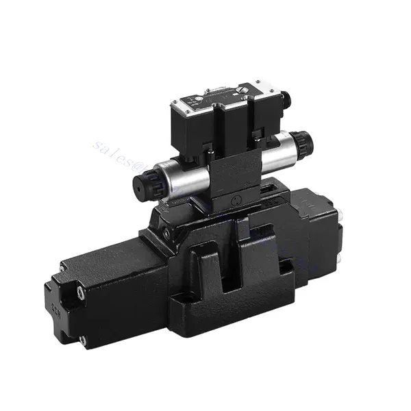
4WRZ/H(E)-serien pilotstyrd proportionell riktningshydraulisk ventil
Som en av tillverkarna, leverantörerna och exportörerna av mekaniska produkter erbjuder vi hydraulcylindrar och många andra produkter.
Vänligen kontakta oss för mer information.
E-post:sales@hydraulic-cylinders.net
Tillverkare, leverantör och exportör av hydraulcylindrar.
4WRZ/H(E)-serien pilotstyrd proportionell riktningshydraulisk ventil
The 4WRZ/H(E) series pilot-operated proportional directional hydraulic valve is a state-of-the-art component designed to provide exceptional precision, control, and efficiency in hydraulic systems. With its advanced pilot-operated proportional control technology, this valve enables accurate flow regulation and seamless directional changes.
The 4WRZ/H(E) series pilot-operated proportional directional hydraulic valve empowers hydraulic systems with precise flow control, versatile directional changes, and energy efficiency. Its pilot-operated proportional control technology ensures accurate and responsive flow adjustment, while the high flow capacity guarantees reliable performance even in demanding applications. By following the recommended usage methods and maintenance guidelines, you can maximize the benefits and longevity of the 4WRZ/H(E) series valve, elevating your hydraulic system to new levels of precision and control. Upgrade your hydraulic setup today and experience the power of the 4WRZ/H(E) series pilot-operated proportional directional hydraulic valve.
4WRZ/H(E) Series Pilot Operated Proportional Directional Hydraulic Valve Key Characteristics:
- Pilotstyrd proportionell styrning
- The 4WRZ/H(E) series valve utilizes pilot-operated proportional control technology, allowing precise and proportional flow adjustment based on control signals.
- Denna funktion säkerställer noggrann och responsiv styrning, vilket resulterar i förbättrad systemprestanda, minskad energiförbrukning och ökad produktivitet.
- Mångsidig riktningskontroll
- Denna ventil erbjuder mångsidig kontroll över hydraulvätskeriktningen, vilket gör den lämplig för en mängd olika tillämpningar.
- Det möjliggör sömlös aktivering och avaktivering av hydrauliska komponenter som cylindrar, motorer och ställdon i olika riktningar, vilket förbättrar systemets flexibilitet och anpassningsförmåga.
- Hög flödeskapacitet
- The 4WRZ/H(E) series valve is engineered to handle high flow rates, making it ideal for applications that require substantial hydraulic power.
- Dess robusta konstruktion säkerställer tillförlitlig prestanda även under krävande förhållanden, vilket ger en konsekvent och effektiv flödeskontroll.
- Energieffektivitet
- Genom att integrera pilotstyrd proportionell styrning minimerar denna ventil tryckfall och optimerar energianvändningen.
- Det bidrar till att minska energiförbrukningen, vilket resulterar i kostnadsbesparingar och miljöfördelar.
4WRZ/H(E) Series Pilot Operated Proportional Directional Hydraulic Valve Parameter:
| GeneraL | |||||||
| Valve type | WRZ | WRZE | |||||
| Installation | Optional,preferably horizontal | ||||||
| Förvaringstemperaturintervall | ℃ | -20 till +80 | |||||
| Omgivningstemperaturintervall | ℃ | -20 to +70 | -20 till +50 | ||||
| Vikt | NS 10 | kg | 7.8 | 8 | |||
| NS 16 | kg | 13.4 | 13.6 | ||||
| NS 25 | kg | 18.2 | 18.4 | ||||
| NS 32 | kg | 42.2 | 42.4 | ||||
| Hydraulisk (measured with HLPAG.p=100bar : 40 ℃ ± 5 ℃) | |||||||
| Storlek | 10 | 16 | 25 | 32 | |||
| Driftstryck | Pilot valve | External pilot oil supply | bar | 30 to 100 bar | |||
| Internal pilot oil supply | bar | 100 to 350 with “D3” only | |||||
| Huvudventil | bar | to 315 | to 350 | to 350 | to 350 | ||
| Returtryck | Port T (Port R) (external pilot oil drain)) | bar | to 315 | to 250 | to 250 | till 150 | |
| Port T (internal pilot oil drain) | bar | to 30 | to 30 | to 30 | to 30 | ||
| Port Y | bar | to 30 | to 30 | to 30 | to 30 | ||
| Pilot oil volume input signal 0- 100 % | cm3 | 1.7 | 4.6 | 10 | 26.5 | ||
| Pilot oil flow in port X and Y with a stepped input signal 0- 100 % | 3.5 | 5.5 | 7 | 15.9 | |||
| Flow of the main valve | l/min | to 170 | to 460 | to 870 | to 1600 | ||
| Hydraulvätska | l/min | Mineral oil (HL, HLP) to DIN 51524 Further fluids on enquiry | |||||
| Temperaturområde för hydraulvätska | ℃ | -20 to +80(preferably +40 to +50) | |||||
| Viskositetsområde | mm2/s | 20 to 380(preferably 30 to 46) | |||||
| Grad av kontaminering | Maximum permissible degree of contamination of the pressure fluid is to NAS 1638 or ISO 4406(c) | A filter with a minimum retention rate of βx ≥ 75 is recommended | |||||
| Pilot valve | NAS 1638 class 7 | x=5 | |||||
| Huvudventil | NAS 1638 class 9 | x=15 | |||||
| Hysteres | % | ≤6 | |||||
| Elektrisk | |||||||
| Valve type | WRZ | WRZE | |||||
| Type of protection of the valve to EN 60529 | IP65 with cable socket mounted and locked | ||||||
| Spänningstyp | likström | ||||||
| Command value overlap | % | 15 | |||||
| Max. current | En | 1.5 | 2.5 | ||||
| Solenoid coil resisance | Cold value at 20℃ | Ω | 4.8 | 2 | |||
| Max. värmevärde | Ω | 7.2 | 3 | ||||
| Cyklisk varaktighetsfaktor | % | 100 | |||||
| Spoltemperatur | ℃ | till 150 | |||||
| Ventilskydd enligt EN 60529 | IP65 | ||||||
| Styrelektronik | |||||||
| External amplifier for type WRZ | VT- VSPA2-L2X/… | ||||||
| Kommandovärdessignal | -Voltage input “A1” | V | ±10 | ||||
| –Current input “F1” | mA | 4 to 20 | |||||
4WRZ/H(E) Series Pilot Operated Proportional Directional Hydraulic Valve Advantages:
• Pilot-operated two-stage proportional directional valve, used to control the size and direction of the liquid flow
• Threaded connection type proportional solenoid, the coil can be disassembled separately
• Sub-plate mounting connection structure, connection size conforms to DIN2430 and ISO4401 standards
• Spolfjäderjustering
• WRZE type with integrated proportional amplifierr
• WRZ type external amplifier (order separately)
Usage Method Of 4WRZ/H(E) Series Pilot Operated Proportional Directional Hydraulic Valve:
- Systemutvärdering
- Utvärdera ditt hydraulsystem och identifiera de specifika kraven för flödes- och riktningskontroll.
- Determine if the 4WRZ/H(E) series valve is suitable based on its flow capacity, pressure rating, and compatibility with your system.
- Ventilval
- Select the appropriate variant of the 4WRZ/H(E) series valve based on your system parameters, flow requirements, and directional control needs.
- Tänk på faktorer som maximal flödeshastighet, tryckklassning, reaktionstid och driftsförhållanden.
- Installation
- Följ tillverkarens installationsanvisningar noggrant och säkerställ korrekt inriktning och säker montering av ventilen.
- Gör läckagefria anslutningar och säkerställ att flödesriktningen är korrekt inställd för att garantera optimal prestanda.
- Anslutning av styrsignal
- Anslut ventilens styrsignalledningar till en lämplig styrenhet, såsom en proportionalförstärkare eller elektronisk styrenhet.
- Säkerställ korrekt kabeldragning och kompatibilitet mellan ventilen och styrenheten för noggrann och responsiv styrning.
How To Bleed Hydraulic Control Valve?
Bleeding a hydraulic control valve is an essential maintenance procedure to remove any trapped air or gas from the system, ensuring optimal performance and efficiency. Here’s a step-by-step guide on how to bleed a hydraulic control valve:
- Förbered systemet:
- Ensure that the hydraulic system is turned off and that the pressure is relieved. This step is crucial for your safety and to prevent any accidental movement or release of high-pressure fluids.
- Locate the bleeder valve or bleed screw on the hydraulic control valve. It is typically located on the top or side of the valve body and may have a protective cap or cover.
- Positioning and Safety Measures:
- Place a suitable container or absorbent material beneath the bleed valve to catch any fluid that may be expelled during the bleeding process.
- Wear appropriate personal protective equipment (PPE), such as safety goggles and gloves, to protect yourself from hydraulic fluid splashes.
- Opening the Bleed Valve:
- Using an appropriate wrench or tool, carefully loosen the bleed valve or screw counterclockwise. Be cautious not to fully remove it at this stage.
- The bleed valve may have an O-ring or sealing washer. Take note of its position and ensure it is in good condition.
- System Activation:
- Activate the hydraulic system by turning on the power source, such as an engine or hydraulic pump.
- Operate the control mechanism associated with the hydraulic control valve, such as a joystick or lever, to allow fluid flow through the valve.
- Bleeding Process:
- Slowly open the bleed valve by turning it counterclockwise until you start to see hydraulic fluid or air bubbles escaping from the valve.
- Allow the fluid to flow for a few seconds or until you observe a steady stream of fluid without any air bubbles. This indicates that the air has been purged from the system.
- Be cautious not to open the bleed valve too much, as it may lead to excessive fluid loss or system damage.
- Closing the Bleed Valve:
- Once you have successfully bled the system, close the bleed valve by turning it clockwise. Ensure it is tightened securely but avoid over-tightening.
- Check for any leaks around the bleed valve or other connections. If you notice any leaks, address them promptly to prevent further issues.
- System Check:
- Turn off the hydraulic system and inspect the fluid level in the reservoir. Add hydraulic fluid as necessary to maintain the recommended level.
- Test the operation of the hydraulic control valve and associated components to ensure proper functionality.
Fabrikens kapacitet och kapacitet:
(1) Montering
Vi har en förstklassig oberoende forsknings- och utvecklingsplattform. Verkstaden för tillverkning av hydraulcylindrar har fyra halvautomatiska monteringslinjer för lyftcylindrar och en automatisk monteringslinje för tiltcylindrar, med en planerad årlig produktionskapacitet på 1 miljon enheter. Specialcylinderverkstaden är utrustad med olika specifikationer för ett halvautomatiskt rengöringsmonteringssystem med en planerad årlig produktionskapacitet på 200 000 och utrustad med känd CNC-bearbetningsutrustning, ett fleroperationscenter, en specialutrustning för högprecisionscylindrar, en robotsvetsmaskin, en automatisk rengöringsmaskin, en automatisk cylindermonteringsmaskin och en automatisk produktionslinje för målning. Befintlig kritisk utrustning på mer än 300 set (set). Optimal allokering och effektiv användning av utrustningsresurser säkerställer produkternas noggrannhetskrav och uppfyller produkternas höga kvalitetsbehov.


(2) Maskinbearbetning
Bearbetningsverkstaden är utrustad med en specialanpassad svarvcentral för lutande räls, bearbetningscenter, höghastighetshönsmaskin, svetsrobot och annan relaterad utrustning, som kan hantera bearbetning av cylinderrör med en maximal innerdiameter på 400 mm och en maximal längd på 6 meter.

(3) Svetsning

(4) Målning och ytbehandling
Med små och medelstora cylindriska automatiska vattenbaserade färgbeläggningslinjer, för att uppnå automatisk robotlastning och lossning samt automatisk sprutning, är den designade kapaciteten 4000 stycken per skift;
Vi har även en halvautomatisk färgproduktionslinje för stora cylindrar som drivs av en släpkedja, med en designkapacitet på 60 lådor per skift.


(5) Testning
Vi har förstklassiga inspektionsanläggningar och testbäddar för att säkerställa att cylinderns prestanda uppfyller kraven.

Vi är en av de bästa tillverkarna av hydraulcylindrar. Vi kan erbjuda ett heltäckande utbud av hydraulcylindrar. Vi tillhandahåller även motsvarande jordbruksväxellådorVi har exporterat våra produkter till kunder över hela världen och fått ett gott rykte tack vare vår överlägsna produktkvalitet och kundservice. Vi välkomnar kunder både hemma och utomlands att kontakta oss för att förhandla affärer, utbyta information och samarbeta med oss!
Hydraulcylinderapplikation:
