

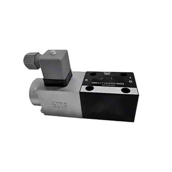
DBETX-serien proportionell tryckavlastningshydraulventil
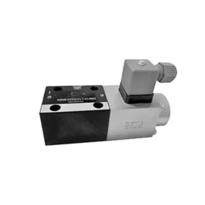

The DBETX series proportional pressure relief hydraulic valve is a versatile and high-performance hydraulic component designed to provide precise pressure relief in hydraulic systems. Engineered with advanced proportional control technology, this valve ensures optimal performance, efficiency, and safety.
The DBETX series proportional pressure relief hydraulic valve empowers hydraulic systems with precise pressure control, enhanced efficiency, and equipment protection. With its proportional pressure relief capabilities, this valve ensures optimal performance across a wide range of applications. By following the recommended usage methods and maintenance guidelines, you can maximize the benefits and reliability of the DBETX series valve, elevating the performance and control of your hydraulic system. Upgrade your hydraulic setup today and experience superior pressure regulation with the DBETX series proportional pressure relief hydraulic valve.
DBETX Series Proportional Pressure Relief Hydraulic Valve Key Characteristics:
- Proportionell tryckavlastning:
- The DBETX series valve delivers proportional pressure relief, allowing for accurate and dynamic hydraulic pressure control.
- It ensures precise pressure regulation in response to varying load conditions, preventing damage to hydraulic components and optimizing system performance.
- Förbättrad systemeffektivitet:
- This valve enables precise control of hydraulic flow rates, resulting in enhanced system efficiency and reduced energy consumption.
- Maintaining the desired pressure levels minimizes pressure fluctuations, enhances overall productivity, and reduces operational costs.
- Säkerhet och utrustningsskydd:
- The DBETX series valve acts as a safeguard by limiting the pressure within the hydraulic system, protecting equipment and operators from potential damage or accidents.
- It prevents overloading and ensures the longevity of hydraulic components, reducing the risk of system failures and downtime.
- Brett användningsområde:
- With its versatile design and compatibility with various hydraulic systems, the DBETX series valve can be used in a wide range of applications across industries such as manufacturing, construction, agriculture, and more.
- It offers flexibility and adaptability, making it suitable for diverse hydraulic setups and requirements.
DBETX Series Proportional Pressure Relief Hydraulic Valve Parameter:
| Allmän | ||||||
| Konstruktion | Poppet valve, direct drive | |||||
| Aktivering | Proportionell solenoid utan positionsreglering, extern förstärkare | |||||
| Anslutningstyp | Subplate, mounting hole configuration NG6 (ISO 4401-03-02-0-94) | |||||
| Installationsposition | Frivillig | |||||
| Omständigheter temperaturintervall | ℃ | -20…+50 | ||||
| Vikt | kg | about 2.1 | ||||
| Vibrationstålighet, testförhållanden | Max. 25 g, shaken in 3 dimensions(24 h) | |||||
| Hydraulic (measured with HLP 46, Voil=40℃±5℃) | ||||||
| Tryckvätska | Hydraulolja enligt DIN 51524…535, andra vätskor efter föregående samråd | |||||
| Viskositetsområde | rekommenderad | 20…100 | ||||
| max. tillåtet | 10…800 | |||||
| Tryckvätsketemperaturområde | ℃ | -20…+80 | ||||
| Maximum permitted degree of contamination of pressure fluid Purity class to ISO 4406(c) | Klass 18/16/13 | |||||
| Flödesriktning | Se symbolen | |||||
| Max. setting pressure (Q = 1 l/min) | bar | 50 | 80 | 180 | 250 | 315 |
| Min. settable pressure (Q = 1 l/min) | bar | 2 | 3 | 4 | 5 | 8 |
| Max. operating pressure(Q = 1 l/min) | bar | Port P: 315 | ||||
| Max. pressure | bar | Port T: 250 | ||||
| Max. mechanical pressure limitation level, e.g. when solenoid current I>Imax | bar | <55 | <85 | <186 | <258 | <325 |
| Statisk/Dynamisk | ||||||
| Hysteres | % | ≤4 | ||||
| Response time 100% signal changen | ms | On<60 / Off<70 | ||||
| Inversionsområde | % | ≤3 | ||||
| Elektriska data | ||||||
| Cyklisk varaktighetsfaktor | % | 100 ED | ||||
| Skyddsgrad | IP 65 enligt DIN 40050 och IEC 14434/5 | |||||
| Solenoidanslutning | Plug-in connector to DIN EN 175301-803/ISO 4400 | |||||
| Driva | 24VDCnom | |||||
DBETX Series Proportional Pressure Relief Hydraulic Valve Advantages:
• Direct, to restrict system pressure
• Can adjust pressure by controlling the current with the solenoid according to the characteristic curve
• In the event of electrical failure, the restricted pressure is still within safety level (solenoid current > Imax)
• External amplifying sub-plate mounting has slope and valve calibration functions (separate order)
Usage Method Of DBETX Series Proportional Pressure Relief Hydraulic Valve:
- Systemutvärdering:
- Evaluate your hydraulic system and identify the specific requirements for pressure control and relief.
- Determine if the DBETX series valve is compatible with your system and suitable for your application based on its pressure range, flow capacity, and other specifications.
- Ventilval:
- Choose the appropriate DBETX series valve variant based on your system parameters, pressure range, and flow requirements.
- Tänk på maximalt tryck, reaktionstid och driftsförhållanden.
- Installation:
- Follow the manufacturer’s installation instructions carefully, ensuring proper alignment and secure valve mounting.
- Anslut ventilen till hydraulsystemet och säkerställ att anslutningarna är läckfria och att flödesriktningen är korrekt inställd.
- Tryckjustering:
- Adjust the pressure relief setting on the DBETX series valve to match the desired pressure range for your application.
- Utilize the proportional control signals or adjustment mechanisms provided with the valve to achieve precise pressure regulation.
How To Adjust A Hydraulic Pressure Relief Valve?
Adjusting a hydraulic pressure relief valve allows you to set the desired maximum pressure in a hydraulic system. This is important for maintaining system integrity and preventing damage to components. Here’s a step-by-step guide on how to adjust a hydraulic pressure relief valve:
- Identifiera tryckavlastningsventilen:
- Locate the pressure relief valve in your hydraulic system. It is typically installed in the hydraulic line and often near the pump or control valve.
- Förstå ventilens design:
- Bekanta dig med den specifika utformningen av den tryckavlastningsventil du arbetar med. Olika ventiler kan ha olika justeringsmekanismer, såsom en ratt, skruv eller låsmutter.
- Bestäm önskat tryck:
- Assess the requirements of your hydraulic system and determine the desired maximum pressure. This will guide you in adjusting the pressure relief valve accurately.
- Förbered systemet:
- Before making any adjustments, shut off the hydraulic system and relieve the pressure by moving the control levers back and forth or following the manufacturer’s recommended procedure.
- Lokalisera justeringsmekanismen:
- Identifiera justeringsmekanismen på tryckavlastningsventilen. Det kan vara en ratt, skruv eller låsmutter placerad på ventilhuset eller intill det.
- Justera ventilen:
- If the valve has a knob or handle, turn it clockwise to increase the pressure relief setting or counterclockwise to decrease it. If the valve has a screw, turn it clockwise to increase the pressure relief or counterclockwise to decrease it.
- Gör stegvisa justeringar:
- When adjusting the pressure relief valve, make small, incremental changes to avoid sudden or drastic variations in pressure. This allows you to fine-tune the maximum pressure and achieve the desired performance.
- Observera systemet:
- With each adjustment, observe the hydraulic system and its components. Pay attention to the pressure gauge readings to see if they align with the desired maximum pressure.
- Testa och verifiera:
- Operate the hydraulic system and monitor the pressure to ensure that it remains within the desired range. Check for any pressure fluctuations or irregularities that may indicate the need for further adjustment.
- Lås justeringen:
- Once you have achieved the desired pressure relief setting, secure the adjustment mechanism to prevent unintended changes. Some valves may have a locking nut or set screw that can be tightened to hold the adjustment in place.
- Monitor and Revisit:
- Regularly monitor the pressure relief valve and the hydraulic system. If there are changes in the system or if the desired maximum pressure needs to be adjusted, revisit the pressure relief valve and repeat the adjustment process as needed.
Fabrikens kapacitet och kapacitet:
(1) Montering
Vi har en förstklassig oberoende forsknings- och utvecklingsplattform. Verkstaden för tillverkning av hydraulcylindrar har fyra halvautomatiska monteringslinjer för lyftcylindrar och en automatisk monteringslinje för tiltcylindrar, med en planerad årlig produktionskapacitet på 1 miljon enheter. Specialcylinderverkstaden är utrustad med olika specifikationer för ett halvautomatiskt rengöringsmonteringssystem med en planerad årlig produktionskapacitet på 200 000 och utrustad med känd CNC-bearbetningsutrustning, ett fleroperationscenter, en specialutrustning för högprecisionscylindrar, en robotsvetsmaskin, en automatisk rengöringsmaskin, en automatisk cylindermonteringsmaskin och en automatisk produktionslinje för målning. Befintlig kritisk utrustning på mer än 300 set (set). Optimal allokering och effektiv användning av utrustningsresurser säkerställer produkternas noggrannhetskrav och uppfyller produkternas höga kvalitetsbehov.


(2) Maskinbearbetning
Bearbetningsverkstaden är utrustad med en specialanpassad svarvcentral för lutande räls, bearbetningscenter, höghastighetshönsmaskin, svetsrobot och annan relaterad utrustning, som kan hantera bearbetning av cylinderrör med en maximal innerdiameter på 400 mm och en maximal längd på 6 meter.


(3) Svetsning


(4) Målning och ytbehandling
Med små och medelstora cylindriska automatiska vattenbaserade färgbeläggningslinjer, för att uppnå automatisk robotlastning och lossning samt automatisk sprutning, är den designade kapaciteten 4000 stycken per skift;
Vi har även en halvautomatisk färgproduktionslinje för stora cylindrar som drivs av en släpkedja, med en designkapacitet på 60 lådor per skift.


(5) Testning
Vi har förstklassiga inspektionsanläggningar och testbäddar för att säkerställa att cylinderns prestanda uppfyller kraven.


Vi är en av de bästa tillverkarna av hydraulcylindrar. Vi kan erbjuda ett heltäckande utbud av hydraulcylindrar. Vi tillhandahåller även motsvarande jordbruksväxellådorVi har exporterat våra produkter till kunder över hela världen och fått ett gott rykte tack vare vår överlägsna produktkvalitet och kundservice. Vi välkomnar kunder både hemma och utomlands att kontakta oss för att förhandla affärer, utbyta information och samarbeta med oss!