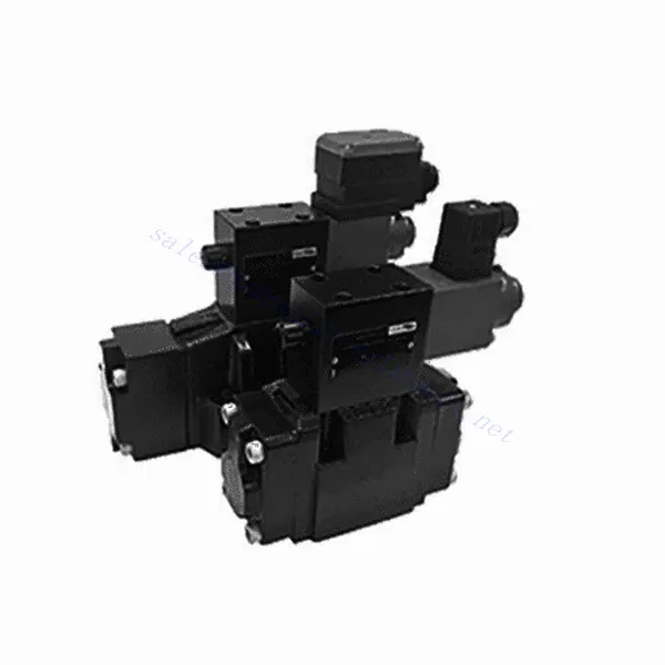
3DRE/M(E) Series 3-way Pilot Operated Proportional Pressure Reducing Hydraulic Valve
3DRE/M(E) Series 3-way Pilot Operated Proportional Pressure Reducing Hydraulic Valve
The 3DRE/M(E) series 3-way pilot-operated proportional pressure-reducing hydraulic valve is a cutting-edge hydraulic component designed to deliver accurate pressure control in hydraulic systems. With its advanced pilot-operated proportional control technology, this valve ensures precise regulation, efficient performance, and reliable operation.
The 3DRE/M(E) series 3-way proportional pressure-reducing hydraulic valve empowers hydraulic systems with precise pressure control, efficiency, and reliable performance. With its advanced proportional control technology and 3-way configuration, this valve offers versatility and flexibility in pressure regulation across different hydraulic circuits. By following the recommended usage methods and maintenance guidelines, you can maximize the benefits and longevity of the 3DRE/M(E) series valve, optimizing pressure control and overall performance in your hydraulic system. Upgrade your hydraulic setup today and experience superior pressure regulation with the 3DRE/M(E) series 3-way proportional pressure-reducing hydraulic valve.
3DRE/M(E) Series 3-way Pilot Operated Proportional Pressure Reducing Hydraulic Valve Key Characteristics:
- Oransal Basınç Kontrolü:
- The 3DRE/M(E) series valve offers precise and proportional pressure control, enabling dynamic adjustment of hydraulic pressure levels.
- This feature ensures accurate pressure regulation, maintaining a consistent and safe pressure within the hydraulic system.
- Pilot Kumandalı Tasarım:
- With its pilot-operated design, the valve delivers enhanced precision and responsiveness in pressure control.
- It utilizes a pilot valve to modulate the main valve, allowing for precise adjustments and improved control over pressure reduction.
- 3-yollu Yapılandırma:
- The 3DRE/M(E) series valve features a versatile 3-way configuration, providing flexibility in controlling pressure across different hydraulic circuits.
- It allows for simultaneous pressure reduction in one circuit while supplying pressure to another course.
- Verimli Performans:
- By utilizing advanced proportional control technology, the valve ensures efficient performance, optimizing energy usage and reducing operational costs.
- It minimizes pressure fluctuations, enhancing system efficiency and contributing to overall productivity.
3DRE/M(E) Series 3-way Pilot Operated Proportional Pressure Reducing Hydraulic Valve Parameter:
| Hidrolik | ||||||||
| Kurulum pozisyonu | isteğe bağlı, tercihen yatay | |||||||
| Boyut | 6 | 10 | ||||||
| Ağırlık | 4WRA…L2X | Kilogram | 2 | 6.6 | ||||
| 4WRAE…L2X | 2.2 | 6.8 | ||||||
| Δp = 10 bar olduğunda nominal akış qnom | L/dak | 7、15、26 | 30、60 | |||||
| Histerezis | % | ≤5 | ||||||
| Tekrarlanabilirlik | % | ≤1 | ||||||
| Tepki duyarlılığı | % | ≤0,5 | ||||||
| Maksimum çalışma basıncı | Limanın ABP'si | çubuk | 315 | |||||
| Liman T | çubuk | 210 | ||||||
| Sıvı | NBR ve FKM contaları için uygun mineral yağ | |||||||
| FKM contası için fosfat esteri | ||||||||
| Sıvı sıcaklık aralığı | 4WRA…L2X | ℃ | -20℃ ila 70℃(-4°F ila 158°F) | |||||
| 4WRAE…L2X | ℃ | -20℃ ila 50℃(-4° F ila 122° F) | ||||||
| Viskozite aralığı | mm²/s | 20 ila 380 (tercihen 30 ila 46) | ||||||
| Kirlilik derecesi | NAS1638 sınıf 9 veya ISO 4406 sınıf 20/18/15 | |||||||
| Elektriksel veriler | ||||||||
| 1)solenoid | ||||||||
| Voltaj türü | DC | |||||||
| Komut değeri sinyali | ±10V veya 4~20mA | |||||||
| Solenoid başına maksimum akım | A | 2.5 | 1.5 | 0.8 | ||||
| Bobin direnci | Soğuk değer | Ω | 2 | 4.8 | 19.5 | |||
| Maksimum sıcak değer | 3 | 7.2 | 28.8 | |||||
| Görev | % | ED100% | ||||||
| Bobin sıcaklığı | ℃ | 150 | ||||||
| EN 60529'a göre vana koruması | IP 65 | |||||||
| 2)Kontrol elektroniği | ||||||||
| Amplifikatör | 4WRA…L2X | VT-VSPA2-L2X | ||||||
| 4WRAE…L2X | Vanaya entegre (OBE) | |||||||
| Çalışma voltajı | Nominal voltaj | VDC | 24 | |||||
| Alt sınır değeri | V | 21/22(4WRA),19(4WRAE) | ||||||
| Üst sınır değeri | V | 35 | ||||||
| Amplifikatör akım tüketimi | Imax | A | <1.8 | |||||
| Imax | A | 3 | ||||||
3DREP(E) Serisi 3 Yollu Oransal Basınç Düşürücü Hidrolik Valf Avantajları:
• The pilot-operated relief valve is used for the pressure reduction from P to A and the overflow function from A to T.
• Used for bottom sub-plate mounting, driven by proportional solenoid.
• The mounting surface is in accordance with DIN24 340, type A, ISO4401 and CETOP-RP 121H
• The maximum safety pressure is available for selection.
• Spool spring alignmentalignment
• 3DRE electronic controller: european card specification amplifier VT-VSPA1-1/VT-VSPD-1
• Set point the pressure characteristic curve is linear
• 3DRE(M)E series integrated electronic controller
• Setting value caused by manufacturing error-the deviation of the pressure characteristic curve is small
• The slope of the pressure increase and decrease can be adjusted independently
3DREP(E) Serisi 3 Yollu Oransal Basınç Düşürücü Hidrolik Valf Kullanım Yöntemi:
- Sistem Değerlendirmesi:
- Hidrolik sisteminizi değerlendirin ve her devre için özel basınç kontrol gereksinimlerini belirleyin.
- Determine if the 3DRE/M(E) series valve is suitable based on its pressure range, flow capacity, and compatibility with your system.
- Vana Seçimi:
- Select the appropriate variant of the 3DRE/M(E) series valve based on your system parameters, pressure range, and flow requirements.
- Maksimum basınç derecesini, tepki süresini ve çalışma koşullarını göz önünde bulundurun.
- Kurulum:
- Üreticinin montaj talimatlarını dikkatlice izleyin, doğru hizalamayı ve güvenli vana montajını sağlayın.
- Valfi hidrolik sisteme bağlayın, bağlantıların sızdırmaz olduğundan ve akış yönünün doğru olduğundan emin olun.
- Basınç Ayarı:
- Utilize the pilot valve control mechanism provided with the 3DRE/M(E) series valve to adjust the desired pressure reduction level for each circuit.
- Gradually adjust the pilot valve control to achieve the desired pressure control, monitoring the pressure gauge readings and system response.
How To Adjust Hydraulic Valves?
Adjusting hydraulic valves is a crucial task to ensure proper flow control and system performance in hydraulic applications. Here’s a step-by-step guide on how to adjust hydraulic valves:
- Vanayı Tanımlayın:
- Determine the type of hydraulic valve you need to adjust: pressure relief valve, flow control valve, directional control valve, or any other type.
- Locate the valve within your hydraulic system. It can be positioned near the pump, in the control valve manifold, or within specific hydraulic components.
- Gerekli Araçları Toplayın:
- Before starting the adjustment process, gather the required tools, such as an adjustable wrench, a screwdriver, a pressure gauge (if applicable), and any specialized tools recommended by the valve manufacturer.
- Understand the Valve Function:
- Familiarize yourself with the purpose and function of the valve you are adjusting. Refer to the valve’s technical documentation or consult the manufacturer’s guidelines for specific details.
- Determine the Desired Setting:
- Identify the desired setting or parameter you want to achieve by adjusting the valve. This could be pressure, flow rate, direction, or any other adjustable parameter based on the valve type.
- Preliminary Checks:
- Ensure that the hydraulic system is depressurized before attempting any adjustments. This can be done by shutting down the system and relieving residual pressure through appropriate valves.
- Access the Adjustment Mechanism:
- Locate the adjustment mechanism on the valve. It can be a set screw, locknut, knob, or other similar devices depending on the valve type.
- Some valves may require removing a protective cap or cover to access the adjustment mechanism.
- Artımlı Ayarlamalar Yapın:
- Using the appropriate tool, make small incremental adjustments to the valve according to the desired setting.
- Follow the manufacturer’s guidelines to determine the direction (clockwise or counterclockwise) and the amount of adjustment required.
- Make gradual adjustments and periodically check the system’s response to ensure you are moving in the desired direction.
- Test and Monitor:
- After each adjustment, activate the hydraulic system and observe its performance.
- Use appropriate measurement tools (pressure gauge, flow meter, etc.) to verify that the valve is operating within the desired range.
- Monitor the system for any abnormalities or unexpected behavior. If necessary, make further adjustments to fine-tune the valve setting.
- Lock the Adjustment (if applicable):
- Once you achieve the desired setting, secure the adjustment mechanism to prevent unintended changes.
- This can be done by tightening a locknut, securing a set screw, or using any other method recommended by the valve manufacturer.
Fabrikanın Kapasitesi ve Kapasitesi:
(1) Meclis
Birinci sınıf bağımsız bir araştırma ve geliştirme montaj platformumuz bulunmaktadır. Hidrolik silindir üretim atölyemizde, yıllık 1 milyon adet üretim kapasitesine sahip dört adet yarı otomatik kaldırma silindiri montaj hattı ve bir adet otomatik devirme silindiri montaj hattı bulunmaktadır. Özel silindir atölyemiz, yıllık 200.000 adet üretim kapasitesine sahip çeşitli özelliklerde yarı otomatik temizleme montaj sistemiyle donatılmıştır. Ayrıca, ünlü CNC işleme ekipmanları, bir işleme merkezi, yüksek hassasiyetli silindir işleme özel ekipmanları, bir robot kaynak makinesi, bir otomatik temizleme makinesi, otomatik silindir montaj makinesi ve otomatik boyama üretim hattı ile donatılmıştır. 300'den fazla setten oluşan kritik ekipmanlar mevcuttur. Ekipman kaynaklarının optimum dağılımı ve verimli kullanımı, ürünlerin hassasiyet gereksinimlerini karşılar ve ürünlerin yüksek kalite ihtiyaçlarını karşılar.


(2) İşleme
İşleme atölyesi, maksimum 400 mm iç çapa ve maksimum 6 metre uzunluğa sahip silindir borularının işlenmesini gerçekleştirebilen özel eğimli ray torna merkezi, işleme merkezi, yüksek hızlı honlama makinesi, kaynak robotu ve diğer ilgili ekipmanlarla donatılmıştır.

(3) Kaynak

(4) Boyama ve kaplama
Küçük ve orta ölçekli silindirli otomatik su bazlı boya kaplama hatlarında, otomatik robot yükleme-boşaltma ve otomatik püskürtmeyi gerçekleştirmek için, vardiya başına 4000 adet tasarım kapasitesi;
Ayrıca, vardiya başına 60 kasa kapasiteli, güç zinciriyle çalışan büyük silindirler için yarı otomatik boya üretim hattımız da bulunmaktadır.


(5) Test etme
Silindirin performansının gereklilikleri karşıladığından emin olmak için birinci sınıf muayene tesislerimiz ve test yataklarımız bulunmaktadır.

En iyi hidrolik silindir üreticilerinden biriyiz. Kapsamlı hidrolik silindirler sunabiliyoruz. Ayrıca, ilgili hidrolik silindirleri de sağlıyoruz. tarımsal dişli kutularıÜrünlerimizi dünya çapındaki müşterilerimize ihraç ettik ve üstün ürün kalitemiz ve satış sonrası hizmetlerimiz sayesinde iyi bir itibar kazandık. Yurt içi ve yurt dışındaki müşterilerimizi iş görüşmeleri yapmak, bilgi alışverişinde bulunmak ve bizimle işbirliği yapın!


