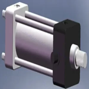
30SD10-40 Solenoid Directional Valve
30SD10-40 Solenoid Directional Valve
The 30SD10-40 solenoid directional valve is a high-performance industrial component designed to deliver precise and reliable fluid control in a variety of applications. With its advanced features, durable construction, and user-friendly design, this solenoid directional valve offers enhanced efficiency and operational reliability.
The 30SD10-40 solenoid directional valve is a reliable and versatile component that offers precise fluid control in industrial applications. Its robust construction, precision control, and reliable performance enhance efficiency and productivity in fluid control systems. By following the recommended usage methods and maintenance guidelines, you can ensure optimal performance and longevity of the 30SD10-40 solenoid directional valve in your industrial operations.
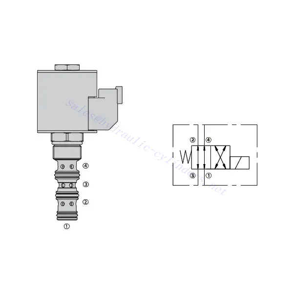
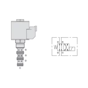
30SD10-40 Solenoid Directional Valve Characteristics:
- Robust Construction: The 30SD10-40 solenoid directional valve is built with exceptional craftsmanship and high-quality materials, ensuring durability and longevity. Its sturdy construction allows it to withstand demanding industrial environments, providing reliable performance even in harsh conditions.
- Versatile Functionality: This solenoid directional valve offers versatile functionality, making it suitable for a wide range of applications. It effectively controls the direction of fluid flow, enabling precise and efficient operation in various industrial systems.
- Precision Control: The 30SD10-40 solenoid directional valve provides exceptional precision in fluid control. It allows for accurate regulation and adjustment of fluid direction and pressure, ensuring optimal performance and efficiency in industrial processes.
- Reliable Performance: This solenoid directional valve delivers reliable performance, minimizing the risk of system failures or interruptions. It operates with dependability, contributing to increased productivity and reduced downtime in industrial operations.
30SD10-40 Solenoid Directional Valve Parameter:
| Anma basıncı | 207 bar (3000 psi) | |
| Tepe akışı | 23 L/dak (6 galon/dakika) | |
| Sıvı | Mineral bazlı veya yağlayıcı özelliklere sahip sentetikler | |
| Temperature range ℃ | -54 ila 107 ℃ (Poliüretan contalar) | |
| -40 ila 100 ℃ (Buna N contaları) | ||
| -26 ila 204 ℃ (Florokarbon contalar) | ||
| Viskozite aralığı | 7,4 ila 420 mm2/S | |
| Kirlilik derecesi | Minimum kirlilik seviyesi ISO4406 seviyesi 20/18/14'tür ve hizmet ömrünü uzatmak için 17/15/13 seviyesi önerilir. | |
| İç Sızıntı | ≤ 82 mL/min@207bar | |
| Boşluk | VC10-4 | |
| Bobin Görev Derecesi | Nominal gerilimin 85%'den 115%'ye kadar sürekli | |
| 20℃'de İlk Bobin Akımı Çekimi | E-bobin | 12 VDC'de 1,7 A; 24 VDC'de 0,85 A |
| D-bobin | 12 VDC'de 1,67 A; 24 VDC'de 0,83 A | |
| Minimum çekme gerilimi | 207 bar'da nominal 85% | |
30SD10-40 Solenoid Directional Valve Advantages:
• Sürekli görev derecesine sahip bobin
• Kartuşlar voltaj değiştirilebilir
• IP69K'ya kadar derecelendirilmiş isteğe bağlı su geçirmez E-Bobinler
• Verimli ıslak armatür yapısı
• Endüstri ortak boşluğu
• Uzun ömür için sertleştirilmiş parçalar
Usage Method Of 30SD10-40 Solenoid Directional Valve :
- Integration into the System: Integrate the 30SD10-40 Solenoid Directional Valve into the fluid control system following the manufacturer’s guidelines and specifications. Ensure proper alignment and connection between the valve and other system components to achieve optimal performance.
- Electrical Connection: Establish a secure electrical connection for the solenoid directional valve. Follow the provided wiring diagram and ensure correct polarity to prevent electrical malfunctions. Adhere to safety guidelines when working with electrical connections.
- Fluid Flow Direction Control: Utilize the solenoid directional valve to control the direction of fluid flow. The valve is typically equipped with a lever or actuator for manual adjustment. Alternatively, it can be integrated into an automated control system for remote operation.
- Pressure Adjustment: Use the solenoid directional valve to regulate fluid pressure within the system. Adjust the valve’s settings to achieve the desired pressure levels for optimal performance and efficiency.
How To Read Hydraulic Valve Schematics?
Reading hydraulic valve schematics requires a basic understanding of hydraulic symbols and their meanings. Here are the steps to help you read hydraulic valve schematics:
- Familiarize Yourself With Hydraulic Symbols: Hydraulic schematics use graphical symbols to represent various components and functions. Common symbols include squares for valves, lines for pipes or hoses, arrows for flow direction, and circles for pressure or flow control devices. Make sure you understand the meaning of these symbols before proceeding.
- Identify The Valve Types: Look for the valve symbols in the schematic. Valves can be represented by squares with different shapes and orientations. For example, a square with a diagonal line represents a check valve, while a square with an arrow inside denotes a directional control valve.
- Determine The Valve Function: Each valve symbol indicates its specific function. Directional control valves determine the flow direction of hydraulic fluid, while pressure control valves regulate pressure levels. Flow control valves manage the rate of fluid flow, and check valves allow flow in one direction only.
- Observe The Valve Connections: Pay attention to the lines or arrows entering and exiting the valve symbol. These lines represent the hydraulic fluid flow paths. Arrows indicate the flow direction, and lines connecting valves and other components indicate the connections.
- Analyze The Valve Ositions: Some hydraulic valve schematics include symbols to illustrate the valve positions. These symbols typically depict the valve spool or lever in different positions, such as open, closed, or partially open. Understanding the valve positions helps you determine the flow paths and the state of the hydraulic system.
- Consider Additional Symbols And Annotations: Hydraulic schematics may include additional symbols and annotations to indicate pressure gauges, flow meters, filters, accumulators, or other components. Familiarize yourself with these symbols and their meanings to gain a comprehensive understanding of the system.
- Follow The Flow Paths: Trace the flow paths from the hydraulic power source through the various valves and components to the actuator or desired output. Understand how the valves interact with one another and how they control fluid flow, pressure, and direction to achieve the desired system operation.
- Refer To The Legend Or Key: The schematic should have a legend or key that explains the meaning of each symbol used in the diagram. If you encounter unfamiliar symbols or have doubts about their meaning, refer to the legend for clarification.
- Seek Additional Resources If Needed: If you need a more in-depth understanding of hydraulic valve schematics, consider referring to hydraulic textbooks, online resources, or consulting with hydraulic experts who can provide guidance and explanations tailored to your specific needs.
Fabrikanın Kapasitesi ve Kapasitesi:
(1) Meclis
Birinci sınıf bağımsız bir araştırma ve geliştirme montaj platformumuz bulunmaktadır. Hidrolik silindir üretim atölyemizde, yıllık 1 milyon adet üretim kapasitesine sahip dört adet yarı otomatik kaldırma silindiri montaj hattı ve bir adet otomatik devirme silindiri montaj hattı bulunmaktadır. Özel silindir atölyemiz, yıllık 200.000 adet üretim kapasitesine sahip çeşitli özelliklerde yarı otomatik temizleme montaj sistemiyle donatılmıştır. Ayrıca, ünlü CNC işleme ekipmanları, bir işleme merkezi, yüksek hassasiyetli silindir işleme özel ekipmanları, bir robot kaynak makinesi, bir otomatik temizleme makinesi, otomatik silindir montaj makinesi ve otomatik boyama üretim hattı ile donatılmıştır. 300'den fazla setten oluşan kritik ekipmanlar mevcuttur. Ekipman kaynaklarının optimum dağılımı ve verimli kullanımı, ürünlerin hassasiyet gereksinimlerini karşılar ve ürünlerin yüksek kalite ihtiyaçlarını karşılar.


(2) İşleme
İşleme atölyesi, maksimum 400 mm iç çapa ve maksimum 6 metre uzunluğa sahip silindir borularının işlenmesini gerçekleştirebilen özel eğimli ray torna merkezi, işleme merkezi, yüksek hızlı honlama makinesi, kaynak robotu ve diğer ilgili ekipmanlarla donatılmıştır.

(3) Kaynak

(4) Boyama ve kaplama
Küçük ve orta ölçekli silindirli otomatik su bazlı boya kaplama hatlarında, otomatik robot yükleme-boşaltma ve otomatik püskürtmeyi gerçekleştirmek için, vardiya başına 4000 adet tasarım kapasitesi;
Ayrıca, vardiya başına 60 kasa kapasiteli, güç zinciriyle çalışan büyük silindirler için yarı otomatik boya üretim hattımız da bulunmaktadır.


(5) Test etme
Silindirin performansının gereklilikleri karşıladığından emin olmak için birinci sınıf muayene tesislerimiz ve test yataklarımız bulunmaktadır.

En iyi hidrolik silindir üreticilerinden biriyiz. Kapsamlı hidrolik silindirler sunabiliyoruz. Ayrıca, ilgili hidrolik silindirleri de sağlıyoruz. tarımsal dişli kutularıÜrünlerimizi dünya çapındaki müşterilerimize ihraç ettik ve üstün ürün kalitemiz ve satış sonrası hizmetlerimiz sayesinde iyi bir itibar kazandık. Yurt içi ve yurt dışındaki müşterilerimizi iş görüşmeleri yapmak, bilgi alışverişinde bulunmak ve bizimle işbirliği yapın!