
G.DBW Series Pilot Operated Explosion-proof Pressure Relief Hydraulic Valve
Hidrolik silindir üreticilerinden, tedarikçilerinden ve mekanik ürünlerin ihracatçılarından biri olarak, hidrolik silindirler ve diğer birçok ürünü sunuyoruz.
Ayrıntılar için lütfen bizimle iletişime geçin.
Posta:sales@hydraulic-cylinders.net
Hidrolik silindir üreticisi tedarikçisi ihracatçısı.
G.DBW Series Pilot Operated Explosion-proof Pressure Relief Hydraulic Valve
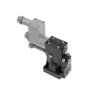
The G.DBW series pilot-operated explosion-proof pressure relief hydraulic valve is a cutting-edge hydraulic component specifically designed for applications in hazardous environments. With its exceptional explosion-proof features and reliable pressure relief capabilities, this valve ensures the utmost safety and performance in critical hydraulic systems.
The G.DBW series pilot-operated explosion-proof pressure relief hydraulic valve is the ultimate solution for ensuring safety and reliability in hazardous environments. With its explosion-proof design, reliable pressure relief capabilities, precise pressure control, and versatility, this valve delivers exceptional performance and protection in critical hydraulic systems; by following the recommended usage methods and maintenance practices, the G.DBW series valve guarantees longevity, safety, and optimal functionality. Upgrade your hydraulic system with the G.DBW series pilot-operated explosion-proof pressure relief hydraulic valve and experience unparalleled safety and reliability in hazardous environments.
G.DBW Series Pilot Operated Explosion-proof Pressure Relief Hydraulic Valve Key Characteristics:
- Patlamaya dayanıklı tasarım:
- The G.DBW series valve is engineered with an explosion-proof design, making it suitable for use in environments where flammable gases or vapors are present.
- It meets rigorous safety standards and complies with industry regulations, reducing the risk of ignition or explosion in hazardous areas.
- Reliable Pressure Relief:
- This valve offers reliable pressure relief capabilities, protecting hydraulic systems from excessive pressure buildup.
- It automatically opens when the system pressure exceeds the set limit, diverting excess fluid to a low-pressure outlet and preventing potential damage or failures.
- Precise Pressure Control:
- The G.DBW series valve provides precise pressure control, allowing operators to set desired pressure levels within hydraulic systems.
- This feature ensures optimal system performance, protecting sensitive components and enhancing efficiency.
- Versatility and Customization:
- The valve is available in various sizes, pressure ratings, and configurations, accommodating various system requirements.
- It offers customization options for specific hydraulic applications, providing flexibility and adaptability.
G.DBW Series Pilot Operated Explosion-proof Pressure Relief Hydraulic Valve Parameter:
| Kurulum pozisyonu | İsteğe bağlı | ||||||
| Ağırlık | G…DBW…10 | G…DBW…15 | G…DBW…20 | G…DBW…25 | G…DBW…30 | ||
| Base sub-plate mounting G…DBW | kilogram | about 5.6 | – | about 6.5 | – | yaklaşık 7.9 | |
| threaded connection G…DBW..G.. | kilogram | yaklaşık 7.9 | about 7.8 | about 7.7 | about 8.5 | about 8.4 | |
| Switching shock damping | kilogram | yaklaşık 0,6 | |||||
| Technical parameters of directional valve | Refer to the solenoid valvetype G…WE6,normally close use G…3WE6A9, normally open use G…3WE6B9 | ||||||
| Sıvı | NBR ve FKM contaları için uygun mineral yağ | ||||||
| FKM contası için fosfat esteri | |||||||
| Sıvı sıcaklık aralığı | ℃ | -30 ila +80 (NBR conta) | |||||
| -20 ila +80(FKM contası) | |||||||
| Viskozite aralığı | mm2/S | 10 ila 800 | |||||
| Kirlilik derecesi | İzin verilen maksimum sıvı kirliliği derecesi: Sınıf 9. NAS 1638 veya 20/18/15, ISO4406 | ||||||
| Maksimum çalışma basıncı | Port A, B, X, P | çubuk | 350 | ||||
| Port Y or T DBW | çubuk | 210 | |||||
| Maksimum ayar basıncı | çubuk | 50; 100; 200; 315; 350 | |||||
| Min. | çubuk | Interrelated with Q(Refer to the characteristic curve) | |||||
| NS (NG) | 10 | 15 | 20 | 25 | 30 | ||
| Maksimum akış hızı | Base Sub-plate mounting | L/dak | 250 | – | 500 | – | 650 |
| threaded connection | L/dak | 250 | 500 | 500 | 500 | 650 | |
G.DBW Series Pilot Operated Explosion-proof Pressure Relief Hydraulic Valve Advantages:
• Alt alt plaka montajında kullanılır
• Installation face follow DIN 24340 E and ISO 6264
• Vidalı bağlantılarda kullanılır, Alt alt plaka montajında kullanılır
• Five pressure ranges
• Unloading operation via a built-on solenoid directional valv
• İki ayar türü: düğme, koruma kapaklı ayar vidası
• Optional switching shock damping
Usage Method Of G.DBW Series Pilot Operated Explosion-proof Pressure Relief Hydraulic Valve:
- Hazardous Environment Evaluation:
- Conduct a thorough evaluation of the hydraulic system’s operating environment to determine if it falls under hazardous classifications.
- Consider factors such as flammable gases, vapors, or combustible dust.
- Compliance and Certification:
- Ensure that the G.DBW series valve meets the necessary explosion-proof and safety standards for the specific hazardous environment.
- Verify compliance with regulatory bodies and obtain the appropriate certifications.
- Vana Seçimi:
- Select the appropriate variant of the G.DBW series valve based on system specifications, including pressure requirements and flow capacity.
- Consider factors such as compatibility with other system components and the desired pressure relief setting.
- Kurulum:
- Follow the manufacturer’s instructions for properly installing the G.DBW series valve in the hydraulic system.
- Ensure secure connections, proper grounding, and adherence to safety guidelines.
Hidrolik Makara Valfi Nasıl Çalışır?
A hydraulic valve is a crucial component in hydraulic systems that controls the flow and direction of hydraulic fluid. It is responsible for regulating the pressure, allowing fluid to pass through, and directing it to various actuators or hydraulic components. The working principle of a hydraulic valve can be summarized as follows:
- Vana Yapısı:
- A hydraulic valve consists of a valve body, which houses the internal components, and a movable valve element, such as a spool or poppet.
- The valve body contains ports, passages, and chambers facilitating fluid flow.
- Fluid Flow Control:
- When hydraulic fluid enters the valve through the inlet port, it encounters the valve element, determining the flow path.
- The valve element can be moved manually, mechanically, or through hydraulic pressure.
- Vana Pozisyonları:
- Hydraulic valves have different positions, including open, closed, and partially open, which control the fluid flow.
- In the closed position, the valve blocks the flow of fluid entirely.
- In the open position, the valve allows fluid to flow freely through the specified ports.
- In the partially open position, the valve restricts or controls the flow rate of the fluid.
- Spool Valve Operation:
- In a spool valve, a cylindrical spool with lands or channels controls the fluid flow.
- By moving the spool within the valve body, different lands align with specific ports, enabling or blocking fluid flow.
- The movement of the spool is typically achieved using mechanical linkage, solenoids, or hydraulic pressure acting on the spool.
- Poppet Valve Operation:
- In a poppet valve, a movable poppet or disc seals or unseals the fluid flow passage.
- When the poppet is in the closed position, it rests against a seat, blocking fluid flow.
- To open the valve, the poppet is moved away from the seat, allowing fluid to flow through the passage.
- Kontrol Mekanizmaları:
- Hydraulic valves can be operated manually, mechanically, or through electrical means.
- Manual control involves levers, knobs, or handles to position the valve element manually.
- Mechanical control utilizes mechanical linkages or actuators to move the valve element.
- Electrical control employs solenoids or other electrically controlled devices to shift the valve element.
- Actuator Control:
- Hydraulic valves direct fluid to various hydraulic actuators, such as cylinders or motors.
- By opening or closing the appropriate valve ports, the hydraulic system can control the movement and operation of the actuators.
- System Stability and Safety:
- Hydraulic valves play a vital role in maintaining system stability and safety.
- Pressure relief valves, for example, protect the system from overpressure by diverting excess fluid to a low-pressure outlet.
Fabrikanın Kapasitesi ve Kapasitesi:
(1) Meclis
Birinci sınıf bağımsız bir araştırma ve geliştirme montaj platformumuz bulunmaktadır. Hidrolik silindir üretim atölyemizde, yıllık 1 milyon adet üretim kapasitesine sahip dört adet yarı otomatik kaldırma silindiri montaj hattı ve bir adet otomatik devirme silindiri montaj hattı bulunmaktadır. Özel silindir atölyemiz, yıllık 200.000 adet üretim kapasitesine sahip çeşitli özelliklerde yarı otomatik temizleme montaj sistemiyle donatılmıştır. Ayrıca, ünlü CNC işleme ekipmanları, bir işleme merkezi, yüksek hassasiyetli silindir işleme özel ekipmanları, bir robot kaynak makinesi, bir otomatik temizleme makinesi, otomatik silindir montaj makinesi ve otomatik boyama üretim hattı ile donatılmıştır. 300'den fazla setten oluşan kritik ekipmanlar mevcuttur. Ekipman kaynaklarının optimum dağılımı ve verimli kullanımı, ürünlerin hassasiyet gereksinimlerini karşılar ve ürünlerin yüksek kalite ihtiyaçlarını karşılar.


(2) İşleme
İşleme atölyesi, maksimum 400 mm iç çapa ve maksimum 6 metre uzunluğa sahip silindir borularının işlenmesini gerçekleştirebilen özel eğimli ray torna merkezi, işleme merkezi, yüksek hızlı honlama makinesi, kaynak robotu ve diğer ilgili ekipmanlarla donatılmıştır.

(3) Kaynak

(4) Boyama ve kaplama
Küçük ve orta ölçekli silindirli otomatik su bazlı boya kaplama hatlarında, otomatik robot yükleme-boşaltma ve otomatik püskürtmeyi gerçekleştirmek için, vardiya başına 4000 adet tasarım kapasitesi;
Ayrıca, vardiya başına 60 kasa kapasiteli, güç zinciriyle çalışan büyük silindirler için yarı otomatik boya üretim hattımız da bulunmaktadır.


(5) Test etme
Silindirin performansının gereklilikleri karşıladığından emin olmak için birinci sınıf muayene tesislerimiz ve test yataklarımız bulunmaktadır.

En iyi hidrolik silindir üreticilerinden biriyiz. Kapsamlı hidrolik silindirler sunabiliyoruz. Ayrıca, ilgili hidrolik silindirleri de sağlıyoruz. tarımsal dişli kutularıÜrünlerimizi dünya çapındaki müşterilerimize ihraç ettik ve üstün ürün kalitemiz ve satış sonrası hizmetlerimiz sayesinde iyi bir itibar kazandık. Yurt içi ve yurt dışındaki müşterilerimizi iş görüşmeleri yapmak, bilgi alışverişinde bulunmak ve bizimle işbirliği yapın!
Hidrolik Silindir Uygulaması:
