Pres Makinesi İçin Hidrolik Sistem
Hidrolik silindir üreticilerinden, tedarikçilerinden ve mekanik ürünlerin ihracatçılarından biri olarak, hidrolik silindirler ve diğer birçok ürünü sunuyoruz.
Ayrıntılar için lütfen bizimle iletişime geçin.
Posta:sales@hydraulic-cylinders.net
Hidrolik silindir üreticisi tedarikçisi ihracatçısı.
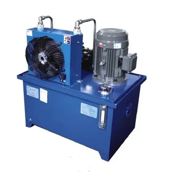
Pres Makinesi İçin Hidrolik Sistem

Hydraulic systems for press machines are cutting-edge solutions designed to optimize productivity, efficiency, and precision for various industrial applications. This advanced hydraulic system uses the power of hydraulic fluids to generate controlled forces, allowing the press to accurately and reliably apply enormous pressures. Let’s delve into the main characteristics, methods of use, maintenance requirements, and other essential aspects of the hydraulic system of the press.
Hydraulic System For Lifter Parameter:

Motor Power:4KW
Oil Tank:120L

Motor Power:15KW
Oil Tank:250L
Özel Hidrolik Sistem Modeli Tanımı:

Petrol Tankının Yapısı:

Yağ Tankı Temizleme Kapağı:

Özel Hidrolik Sistem:
(1)Dikey Hidrolik Sistem

(2)Yatay Hidrolik Sistem

(3) Yan Montajlı Hidrolik Sistem
Yan tarafa monte edilen hidrolik pompa istasyonu, yani yağ pompası cihazı, ayrı bir tank esas alınarak yatay olarak monte edilir ve yan tipte yedek pompa da bulunabilir; bu cihaz esas olarak 250 litrelik büyük bir posta kutusu kapasitesine ve 7,5 kW veya daha fazla elektrik gücüne sahip sistemler için kullanılır.


Kaldırma Platformu İçin Patlamaya Dayanıklı Hidrolik Sistem Özellikler:
- High Force Generation:
- The hydraulic system is designed to provide a high-strength output, enabling the press to apply significant pressure to forming, bending, forming, and other metalworking processes.
- It provides consistent force throughout the stroke, ensuring uniformity, precision, and repeatability in the manufacturing process.
- Çok Yönlü Uygulama:
- The hydraulic systems of presses are suitable for various industrial applications, including metal stamping, forging, stamping, deep drawing, and assembly operations.
- It can be customized to specific requirements, such as tonnage capacity, stroke length and speed, making it suitable for various production needs.
- Hassas Kontrol:
- The system allows precise control of the force and speed of the press, enabling the operator to obtain accurate results and maintain tight tolerances.
- It can adjust pressure Settings, residence time and stroke length for easy customization to the specific needs of the production process.
How Does A Backhoe Hydraulic System Work?
A backhoe hydraulic system is a complex arrangement of components that work together to provide the power and control necessary for the operation of a backhoe. Here’s a simplified explanation of how a backhoe hydraulic system works:
- Hidrolik Pompa:
The system begins with a hydraulic pump, typically driven by the backhoe’s engine. The pump creates pressure by forcing hydraulic fluid (usually oil) into the system. - Hidrolik Sıvı:
The hydraulic fluid is stored in a reservoir and drawn into the pump. It is a medium for transmitting power and lubricating the system’s components. - Kontrol Vanaları:
The hydraulic pump sends pressurized fluid to a series of control valves, which direct fluid flow to different hydraulic cylinders and motors based on the operator’s input. - Hydraulic Cylinders:
Hydraulic cylinders are responsible for converting hydraulic pressure into linear motion. These cylinders are commonly found in the boom, dipper stick, and bucket in a backhoe. When the control valve directs fluid into a cylinder, it extends or retracts, allowing the backhoe to perform digging, lifting, and other operations. - Hydraulic Motors:
Hydraulic motors are used in rotational applications, such as swiveling the backhoe or operating attachments. They convert hydraulic pressure into rotational force. For example, a hydraulic motor may be used to rotate the backhoe’s turntable or drive the wheels on a backhoe loader. - Control Levers:
The operator controls the backhoe’s hydraulic system using control levers or joysticks. These levers actuate the control valves, regulating the flow of hydraulic fluid to the cylinders and motors, enabling precise control of the machine’s movements. - Return Line:
After the hydraulic fluid has performed its work, it returns to the reservoir through the return line. The fluid is filtered to remove contaminants before being recirculated back into the system by the pump. - Güvenlik Özellikleri:
Backhoe hydraulic systems often incorporate safety features such as relief valves and check valves. Relief valves protect the system from excessive pressure by diverting fluid back to the reservoir when the pressure exceeds a predetermined limit. Check valves prevent fluid from flowing in the wrong direction, ensuring that cylinders and motors maintain their positions when not actively engaged.
Fabrikanın Kapasitesi ve Kapasitesi:
(1) Meclis
Birinci sınıf bağımsız bir araştırma ve geliştirme montaj platformumuz bulunmaktadır. Hidrolik silindir üretim atölyemizde, yıllık 1 milyon adet üretim kapasitesine sahip dört adet yarı otomatik kaldırma silindiri montaj hattı ve bir adet otomatik devirme silindiri montaj hattı bulunmaktadır. Özel silindir atölyemiz, yıllık 200.000 adet üretim kapasitesine sahip çeşitli özelliklerde yarı otomatik temizleme montaj sistemiyle donatılmıştır. Ayrıca, ünlü CNC işleme ekipmanları, bir işleme merkezi, yüksek hassasiyetli silindir işleme özel ekipmanları, bir robot kaynak makinesi, bir otomatik temizleme makinesi, otomatik silindir montaj makinesi ve otomatik boyama üretim hattı ile donatılmıştır. 300'den fazla setten oluşan kritik ekipmanlar mevcuttur. Ekipman kaynaklarının optimum dağılımı ve verimli kullanımı, ürünlerin hassasiyet gereksinimlerini karşılar ve ürünlerin yüksek kalite ihtiyaçlarını karşılar.


(2) İşleme
İşleme atölyesi, maksimum 400 mm iç çapa ve maksimum 6 metre uzunluğa sahip silindir borularının işlenmesini gerçekleştirebilen özel eğimli ray torna merkezi, işleme merkezi, yüksek hızlı honlama makinesi, kaynak robotu ve diğer ilgili ekipmanlarla donatılmıştır.

(3) Kaynak

(4) Boyama ve kaplama
Küçük ve orta ölçekli silindirli otomatik su bazlı boya kaplama hatlarında, otomatik robot yükleme-boşaltma ve otomatik püskürtmeyi gerçekleştirmek için, vardiya başına 4000 adet tasarım kapasitesi;
Ayrıca, vardiya başına 60 kasa kapasiteli, güç zinciriyle çalışan büyük silindirler için yarı otomatik boya üretim hattımız da bulunmaktadır.


(5) Test etme
Silindirin performansının gereklilikleri karşıladığından emin olmak için birinci sınıf muayene tesislerimiz ve test yataklarımız bulunmaktadır.

Biz, en iyi hidrolik sistem üreticilerinden biriyiz. Kapsamlı hidrolik sistemler sunabiliyoruz. Ayrıca ilgili parçaları da sağlıyoruz. tarımsal dişli kutularıÜrünlerimizi dünya çapındaki müşterilerimize ihraç ettik ve üstün ürün kalitemiz ve satış sonrası hizmetlerimiz sayesinde iyi bir itibar kazandık. Yurt içi ve yurt dışındaki müşterilerimizi iş görüşmeleri yapmak, bilgi alışverişinde bulunmak ve bizimle işbirliği yapın!
Hidrolik Silindir Uygulaması:
