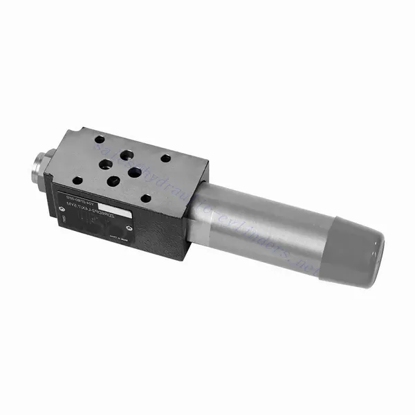
ZDR Series Direct Operated Pressure Reducing Hydraulic Valve
Hidrolik silindir üreticilerinden, tedarikçilerinden ve mekanik ürünlerin ihracatçılarından biri olarak, hidrolik silindirler ve diğer birçok ürünü sunuyoruz.
Ayrıntılar için lütfen bizimle iletişime geçin.
Posta:sales@hydraulic-cylinders.net
Hidrolik silindir üreticisi tedarikçisi ihracatçısı.
ZDR Series Direct Operated Pressure Reducing Hydraulic Valve
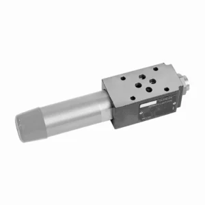
The ZDR series direct-operated pressure-reducing hydraulic valve is a highly efficient and reliable component that provides accurate pressure control in hydraulic systems. With its direct-operated design and exceptional performance, this valve ensures precise pressure reduction to meet specific system requirements.
The ZDR series direct-operated pressure-reducing hydraulic valve is a high-performance solution for precise pressure control in hydraulic systems. With its direct-operated design, accurate pressure control, wide pressure range, and high flow capacity, this valve ensures efficient and reliable pressure reduction while protecting system components. By following the recommended usage methods and maintenance practices, the ZDR series valve delivers reliable performance, extending the lifespan of hydraulic systems. Upgrade your hydraulic system with the ZDR series direct-operated pressure-reducing hydraulic valve and experience optimal pressure control for enhanced system efficiency and productivity.
ZDR Series Direct Operated Pressure Reducing Hydraulic Valve Key Characteristics:
- Doğrudan Çalıştırılan Tasarım:
- The ZDR series valve features a direct-operated design, which enables it to provide precise pressure control without the need for external pilot circuits.
- This design simplifies installation and reduces complexity in hydraulic systems.
- Accurate Pressure Control:
- This valve offers exceptional accuracy in pressure control, allowing hydraulic systems to maintain the desired pressure range with high reliability.
- It ensures stable operation and protects sensitive system components from excessive pressure.
- Geniş Basınç Aralığı:
- The ZDR series valve is available in various pressure ranges, making it suitable for diverse hydraulic applications.
- The flexibility in pressure range allows customization to match specific system requirements and optimize performance.
- Yüksek Akış Kapasitesi:
- This valve exhibits excellent flow capacity, enabling it to handle high flow rates while maintaining precise pressure control.
- It ensures efficient fluid regulation and uninterrupted system operation, even in demanding applications.
ZDR Series Direct Operated Pressure Reducing Hydraulic Valve Parameter:
| Özellikler | NG10 | NG16 | ||
| Sıvı | NBR ve FKM contaları için uygun mineral yağ | |||
| FKM contası için fosfat esteri | ||||
| Sıvı sıcaklık aralığı | ℃ | -30 ila +80 (NBR contalar) | ||
| -20 ila +80 (FKM contaları) | ||||
| Viskozite aralığı | mm2/S | 10 ila 800 | ||
| Kirlilik derecesi | İzin verilen maksimum sıvı kirliliği derecesi: Sınıf 9. NAS 1638 veya 20/18/15, ISO4406 | |||
| Nominal pressure | çubuk | 315 | ||
| Maksimum çalışma basıncı | Liman P | çubuk | 315 | |
| Maksimum çalışma basıncı | A Limanı | çubuk | 315 | 250 |
| Maksimum çalışma basıncı | Liman Y | çubuk | Separate and at zero pressure to tank | |
| Ayar basıncı | Min. | çubuk | Dependent on the flow (see curves) | |
| Max. | çubuk | 50; 100; 200; 315 | 50; 100; 200; 250 | |
| Maksimum akış hızı | L/dak | 120 | 220 | |
| Ağırlık | kilogram | about 6.5 | about 8.8 | |
ZDR Series Direct Operated Pressure Reducing Hydraulic Valve Advantages:
• Sandviç tipi yapı
• Installation face follow DIN 24340 A and ISO 4401
• Dört basınç aralığı
• İki ayar türü: düğme, koruma kapaklı ayar vidası
• With pressure gauge interface
• Optional one directional valve
Usage Method Of ZDR Series Direct Operated Pressure Reducing Hydraulic Valve:
- Sistem Analizi:
- Gerekli basınç kontrolünü belirlemek için kapsamlı bir hidrolik sistem analizi gerçekleştirin.
- Maksimum çalışma basıncını, istenen basınç aralığını ve akış hızlarını göz önünde bulundurun.
- Vana Seçimi:
- Select the appropriate ZDR series valve variant based on the system’s pressure control specifications.
- Basınç derecesini, akış kapasitesini ve diğer sistem bileşenleriyle uyumluluğu göz önünde bulundurun.
- Kurulum:
- Follow the manufacturer’s instructions to correctly install the ZDR series direct-operated pressure-reducing valve in the hydraulic system.
- Sızıntıları önlemek ve performansı optimize etmek için doğru hizalamayı ve güvenli bağlantıları sağlayın.
- Calibration:
- Calibrate the valve to set the desired downstream pressure.
- Utilize pressure gauges or other measurement devices to adjust the valve for optimal pressure control accurately.
How Does A Hydraulic Selector Valve Work?
A hydraulic selector valve, also known as a hydraulic diverter valve or hydraulic control valve, is a device used to direct the flow of hydraulic fluid in a hydraulic system. It allows the operator to control the path of fluid flow by selecting different hydraulic circuits or components to operate. Here’s a breakdown of how a hydraulic selector valve works:
- Vana Yapısı:
- A hydraulic selector valve consists of a body with multiple ports and internal passages.
- It typically has an actuating mechanism, such as a lever or a solenoid, to control the movement of the valve spool or poppet.
- Port Configuration:
- A selector valve has multiple ports, usually labeled as A, B, and C, or sometimes referred to as P, T, and A/B/C.
- Port P (Pressure) connects to the hydraulic pump or the high-pressure side of the system.
- Port T (Tank) connects to the hydraulic reservoir or the low-pressure side of the system.
- Ports A, B, and C are the output ports that connect to different hydraulic circuits or components.
- Vana Pozisyonları:
- The selector valve has different positions that determine the flow path of the hydraulic fluid.
- Common positions include “A,” “B,” “C,” “AB,” “AC,” and “BC,” depending on the specific valve design.
- Fluid Flow Control:
- When the valve is in the neutral or default position, typically labeled “N,” the fluid flow is blocked, and no flow occurs between any of the ports.
- When the operator actuates the valve by moving the lever or energizing the solenoid, the valve spool or poppet shifts to a different position, enabling fluid flow.
- Flow Path Selection:
- By moving the actuating mechanism, the operator can select the desired flow path.
- For example, when the valve is in position “A,” fluid flows from port P to port A, allowing the hydraulic circuit or component connected to port A to operate.
- Multiple Flow Paths:
- Depending on the specific valve design, a hydraulic selector valve can provide multiple flow paths.
- For instance, in position “AB,” fluid can flow from port P to both ports A and B simultaneously, allowing operation of two separate hydraulic circuits or components.
- Kontrol ve İşletme:
- The actuating mechanism of the selector valve can be manual, where the operator physically moves a lever or knob, or it can be electric or pneumatic, using solenoids or other control devices.
- Electrically controlled selector valves can be integrated into automated systems or controlled remotely.
- System Flexibility:
- Hydraulic selector valves provide flexibility in system design and operation.
- They allow the operator to switch between different hydraulic circuits or components, facilitating tasks such as equipment positioning, attachment control, or switching between different implements.
Fabrikanın Kapasitesi ve Kapasitesi:
(1) Meclis
Birinci sınıf bağımsız bir araştırma ve geliştirme montaj platformumuz bulunmaktadır. Hidrolik silindir üretim atölyemizde, yıllık 1 milyon adet üretim kapasitesine sahip dört adet yarı otomatik kaldırma silindiri montaj hattı ve bir adet otomatik devirme silindiri montaj hattı bulunmaktadır. Özel silindir atölyemiz, yıllık 200.000 adet üretim kapasitesine sahip çeşitli özelliklerde yarı otomatik temizleme montaj sistemiyle donatılmıştır. Ayrıca, ünlü CNC işleme ekipmanları, bir işleme merkezi, yüksek hassasiyetli silindir işleme özel ekipmanları, bir robot kaynak makinesi, bir otomatik temizleme makinesi, otomatik silindir montaj makinesi ve otomatik boyama üretim hattı ile donatılmıştır. 300'den fazla setten oluşan kritik ekipmanlar mevcuttur. Ekipman kaynaklarının optimum dağılımı ve verimli kullanımı, ürünlerin hassasiyet gereksinimlerini karşılar ve ürünlerin yüksek kalite ihtiyaçlarını karşılar.


(2) İşleme
İşleme atölyesi, maksimum 400 mm iç çapa ve maksimum 6 metre uzunluğa sahip silindir borularının işlenmesini gerçekleştirebilen özel eğimli ray torna merkezi, işleme merkezi, yüksek hızlı honlama makinesi, kaynak robotu ve diğer ilgili ekipmanlarla donatılmıştır.

(3) Kaynak

(4) Boyama ve kaplama
Küçük ve orta ölçekli silindirli otomatik su bazlı boya kaplama hatlarında, otomatik robot yükleme-boşaltma ve otomatik püskürtmeyi gerçekleştirmek için, vardiya başına 4000 adet tasarım kapasitesi;
Ayrıca, vardiya başına 60 kasa kapasiteli, güç zinciriyle çalışan büyük silindirler için yarı otomatik boya üretim hattımız da bulunmaktadır.


(5) Test etme
Silindirin performansının gereklilikleri karşıladığından emin olmak için birinci sınıf muayene tesislerimiz ve test yataklarımız bulunmaktadır.

En iyi hidrolik silindir üreticilerinden biriyiz. Kapsamlı hidrolik silindirler sunabiliyoruz. Ayrıca, ilgili hidrolik silindirleri de sağlıyoruz. tarımsal dişli kutularıÜrünlerimizi dünya çapındaki müşterilerimize ihraç ettik ve üstün ürün kalitemiz ve satış sonrası hizmetlerimiz sayesinde iyi bir itibar kazandık. Yurt içi ve yurt dışındaki müşterilerimizi iş görüşmeleri yapmak, bilgi alışverişinde bulunmak ve bizimle işbirliği yapın!
Hidrolik Silindir Uygulaması:
