30SD10-40 Соленоїдний напрямний клапан
30SD10-40 Соленоїдний напрямний клапан
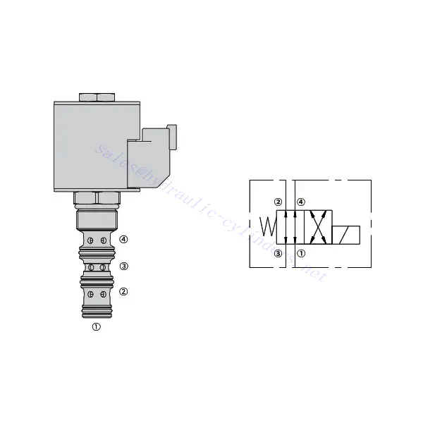
The 30SD10-40 solenoid directional valve is a high-performance industrial component designed to deliver precise and reliable fluid control in a variety of applications. With its advanced features, durable construction, and user-friendly design, this solenoid directional valve offers enhanced efficiency and operational reliability.
The 30SD10-40 solenoid directional valve is a reliable and versatile component that offers precise fluid control in industrial applications. Its robust construction, precision control, and reliable performance enhance efficiency and productivity in fluid control systems. By following the recommended usage methods and maintenance guidelines, you can ensure optimal performance and longevity of the 30SD10-40 solenoid directional valve in your industrial operations.
30SD10-40 Solenoid Directional Valve Characteristics:
- Robust Construction: The 30SD10-40 solenoid directional valve is built with exceptional craftsmanship and high-quality materials, ensuring durability and longevity. Its sturdy construction allows it to withstand demanding industrial environments, providing reliable performance even in harsh conditions.
- Versatile Functionality: This solenoid directional valve offers versatile functionality, making it suitable for a wide range of applications. It effectively controls the direction of fluid flow, enabling precise and efficient operation in various industrial systems.
- Precision Control: The 30SD10-40 solenoid directional valve provides exceptional precision in fluid control. It allows for accurate regulation and adjustment of fluid direction and pressure, ensuring optimal performance and efficiency in industrial processes.
- Reliable Performance: This solenoid directional valve delivers reliable performance, minimizing the risk of system failures or interruptions. It operates with dependability, contributing to increased productivity and reduced downtime in industrial operations.
30SD10-40 Solenoid Directional Valve Parameter:
| Номінальний тиск | 207 бар (3000 фунтів на квадратний дюйм) | |
| Піковий потік | 23 л/хв (6 галонів/хв) | |
| Рідина | На мінеральній основі або синтетичні матеріали зі змащувальними властивостями | |
| Діапазон температур ℃ | від -54 до 107 ℃ (поліуретанові ущільнення) | |
| від -40 до 100 ℃ (ущільнення Buna N) | ||
| від -26 до 204 ℃ (фторвуглецеві ущільнення) | ||
| Діапазон в'язкості | від 7,4 до 420 мм2/с | |
| Ступінь забруднення | Мінімальний рівень забруднення становить ISO4406 20/18/14, а для продовження терміну служби рекомендується рівень 17/15/13. | |
| Внутрішній витік | ≤ 82 mL/min@207bar | |
| Каріозне русло | VC10-4 | |
| Номінальна продуктивність котушки | Безперервний від 85% до 115% номінальної напруги | |
| Початкове споживання струму котушки при 20℃ | Електронна котушка | 1,7 А при 12 В постійного струму; 0,85 А при 24 В постійного струму |
| D-котушка | 1,67 А при 12 В постійного струму; 0,83 А при 24 В постійного струму | |
| Мінімальна напруга втягування | 85% номінального тиску 207 бар | |
30SD10-40 Solenoid Directional Valve Advantages:
• Котушка, розрахована на безперервний режим роботи
• Картриджі можна змінювати за напругою
• Додаткові водонепроникні електронні котушки зі ступенем захисту до IP69K
• Ефективна конструкція з мокрою арматурою
• Загальнопромислова порожнина
• Загартовані деталі для тривалого терміну служби
Usage Method Of 30SD10-40 Solenoid Directional Valve :
- Integration into the System: Integrate the 30SD10-40 Solenoid Directional Valve into the fluid control system following the manufacturer’s guidelines and specifications. Ensure proper alignment and connection between the valve and other system components to achieve optimal performance.
- Electrical Connection: Establish a secure electrical connection for the solenoid directional valve. Follow the provided wiring diagram and ensure correct polarity to prevent electrical malfunctions. Adhere to safety guidelines when working with electrical connections.
- Керування напрямком потоку рідини: Використовуйте електромагнітний розподільний клапан для керування напрямком потоку рідини. Клапан зазвичай оснащений важелем або приводом для ручного регулювання. Крім того, його можна інтегрувати в автоматизовану систему керування для дистанційного керування.
- Pressure Adjustment: Use the solenoid directional valve to regulate fluid pressure within the system. Adjust the valve’s settings to achieve the desired pressure levels for optimal performance and efficiency.
How To Read Hydraulic Valve Schematics?
Reading hydraulic valve schematics requires a basic understanding of hydraulic symbols and their meanings. Here are the steps to help you read hydraulic valve schematics:
- Familiarize Yourself With Hydraulic Symbols: Hydraulic schematics use graphical symbols to represent various components and functions. Common symbols include squares for valves, lines for pipes or hoses, arrows for flow direction, and circles for pressure or flow control devices. Make sure you understand the meaning of these symbols before proceeding.
- Identify The Valve Types: Look for the valve symbols in the schematic. Valves can be represented by squares with different shapes and orientations. For example, a square with a diagonal line represents a check valve, while a square with an arrow inside denotes a directional control valve.
- Determine The Valve Function: Each valve symbol indicates its specific function. Directional control valves determine the flow direction of hydraulic fluid, while pressure control valves regulate pressure levels. Flow control valves manage the rate of fluid flow, and check valves allow flow in one direction only.
- Observe The Valve Connections: Pay attention to the lines or arrows entering and exiting the valve symbol. These lines represent the hydraulic fluid flow paths. Arrows indicate the flow direction, and lines connecting valves and other components indicate the connections.
- Analyze The Valve Ositions: Some hydraulic valve schematics include symbols to illustrate the valve positions. These symbols typically depict the valve spool or lever in different positions, such as open, closed, or partially open. Understanding the valve positions helps you determine the flow paths and the state of the hydraulic system.
- Consider Additional Symbols And Annotations: Hydraulic schematics may include additional symbols and annotations to indicate pressure gauges, flow meters, filters, accumulators, or other components. Familiarize yourself with these symbols and their meanings to gain a comprehensive understanding of the system.
- Follow The Flow Paths: Trace the flow paths from the hydraulic power source through the various valves and components to the actuator or desired output. Understand how the valves interact with one another and how they control fluid flow, pressure, and direction to achieve the desired system operation.
- Refer To The Legend Or Key: The schematic should have a legend or key that explains the meaning of each symbol used in the diagram. If you encounter unfamiliar symbols or have doubts about their meaning, refer to the legend for clarification.
- Seek Additional Resources If Needed: If you need a more in-depth understanding of hydraulic valve schematics, consider referring to hydraulic textbooks, online resources, or consulting with hydraulic experts who can provide guidance and explanations tailored to your specific needs.
Можливості та потужність заводу:
(1) Асамблея
Ми маємо першокласну незалежну платформу для досліджень та розробок. Цех виробництва гідравлічних циліндрів має чотири напівавтоматичні лінії складання підйомних циліндрів та одну автоматичну лінію складання нахилених циліндрів з проектною річною виробничою потужністю 1 мільйон одиниць. Цех спеціальних циліндрів оснащений різними специфікаціями напівавтоматичної системи очищення та складання з проектною річною виробничою потужністю 200 000 одиниць, а також оснащений відомим обладнанням з ЧПУ, обробним центром, високоточним спеціальним обладнанням для обробки циліндрів, роботизованим зварювальним апаратом, автоматичною машиною очищення, автоматичною машиною складання циліндрів та автоматичною виробничою лінією фарбування. Існуюче критично важливе обладнання налічує понад 300 комплектів. Оптимальний розподіл та ефективне використання ресурсів обладнання забезпечує вимоги до точності продукції та задоволення потреб у високій якості продукції.


(2) Механічна обробка
Механічний цех оснащений спеціалізованим токарним центром для похилих рейок, обробним центром, високошвидкісним хонінгувальним верстатом, зварювальним роботом та іншим супутнім обладнанням, яке може обробляти циліндричні труби з максимальним внутрішнім діаметром 400 мм та максимальною довжиною 6 метрів.

(3) Зварювання

(4) Фарбування та покриття
З малими та середніми циліндричними автоматичними лініями нанесення фарби на водній основі, для досягнення автоматичного завантаження та розвантаження роботів та автоматичного розпилення, проектна потужність 4000 штук за зміну;
У нас також є напівавтоматична лінія з виробництва фарби для великих балонів, що живиться від ланцюга, з проектною потужністю 60 корпусів за зміну.


(5) Тестування
Ми маємо першокласне обладнання для інспекції та випробувальні стенди, щоб гарантувати, що характеристики циліндра відповідають вимогам.

Ми є одним з найкращих виробників гідравлічних циліндрів. Ми можемо запропонувати комплексні гідравлічні циліндри. Ми також надаємо відповідні сільськогосподарські коробки передачМи експортуємо нашу продукцію клієнтам по всьому світу та заслужили гарну репутацію завдяки високій якості нашої продукції та післяпродажному обслуговуванню. Ми раді вітати клієнтів як удома, так і за кордоном, щоб зв'язатися з нами для ведення бізнесу, обміну інформацією та... співпрацюйте з нами!


