
4WRPEH Series Proportional Directional Hydraulic Valve
Як один з виробників, постачальників та експортерів механічних виробів, ми пропонуємо гідравлічні циліндри та багато інших продуктів.
Будь ласка, зв'яжіться з нами для уточнення деталей.
Пошта:sales@hydraulic-cylinders.net
Виробник, постачальник, експортер гідравлічних циліндрів.
4WRPEH Series Proportional Directional Hydraulic Valve
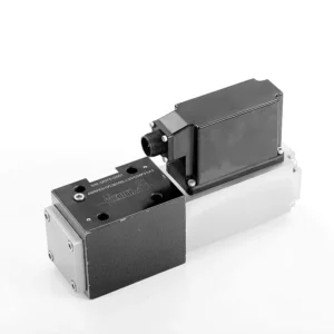
The 4WRPEH series proportional directional hydraulic valve is an advanced hydraulic component designed to deliver exceptional precision and control in hydraulic systems. With its innovative proportional directional control technology, this valve enables accurate flow regulation and smooth directional changes.
The 4WRPEH series proportional directional hydraulic valve empowers hydraulic systems with precise flow control, versatile functionality, and enhanced efficiency. Its proportional directional control technology ensures accurate and responsive flow adjustment, while the high flow capacity guarantees reliable performance even in demanding applications. By following the recommended usage methods and maintenance guidelines, you can maximize the benefits and longevity of the 4WRPEH series valve, elevating your hydraulic system to new levels of precision and control. Upgrade your hydraulic setup today and experience the power of the 4WRPEH series proportional directional hydraulic valve.
4WRPEH Series Proportional Directional Hydraulic Valve Key Characteristics:
- Пропорційне спрямоване керування:
- The 4WRPEH series valve utilizes state-of-the-art proportional directional control technology, allowing precise and proportional flow adjustment based on control signals.
- Ця функція забезпечує точне та швидке керування, що призводить до покращення продуктивності системи, зниження споживання енергії та підвищення продуктивності.
- Універсальний функціонал:
- Цей клапан пропонує універсальне керування напрямком гідравлічної рідини, що робить його придатним для широкого спектру застосувань.
- Це дозволяє безперешкодно активувати та деактивувати гідравлічні компоненти, такі як циліндри, двигуни та виконавчі механізми, у різних напрямках, підвищуючи гнучкість та адаптивність системи.
- Висока пропускна здатність:
- The 4WRPEH series valve is engineered to handle high flow rates, making it ideal for applications that require substantial hydraulic power.
- Його міцна конструкція забезпечує надійну роботу навіть у складних умовах, забезпечуючи стабільний та ефективний контроль потоку.
- Precise Metering:
- With its proportional control technology, this valve offers precise metering of hydraulic fluid, allowing for accurate control and regulation of flow rates.
- This precision enhances overall system performance and ensures precise movements of hydraulic actuators.
4WRPEH Series Proportional Directional Hydraulic Valve Parameter:
НГ6
| Загальне | |||||||
| Дизайн | Золотниковий клапан прямого дії зі сталевою втулкою | ||||||
| Приведення в дію | Пропорційний соленоїд з контролем положення, бортовий | ||||||
| Тип підключення | Монтаж на монтажній плиті, схема підключення портів згідно з ISO 4401-03-02-0-05 | ||||||
| Положення встановлення | Будь-який | ||||||
| Діапазон температур навколишнього середовища | ℃ | -20…+50 | |||||
| Вага | кг | близько 2,75 | |||||
| Максимальна вібростійкість (умова випробування) | Макс. 25 г, випробування на вібрацію в космосі у всіх напрямках (24 год) | ||||||
| Гідравлічний (виміряно при p=100 бар, з HLP46 при ϑолії = 40℃ ±5℃) | |||||||
| Рідина під тиском | Мінеральна олива (HL, HLP) згідно з DIN 51 524 | ||||||
| Діапазон в'язкості | рекомендовано | мм²/с | 20…100 | ||||
| макс. дозволено | мм²/с | 10…800 | |||||
| Діапазон температур рідини під тиском | ℃ | від -20 до +70 | |||||
| Максимально допустимий ступінь забруднення рідини під тиском Клас чистоти згідно з ISO 4406 (c) | Клас 18/16/13 | ||||||
| Номінальний потік (Δp = 35 бар на ребро) | л/хв | 2 | 4 | 12 | 24 | 40 | |
| Макс. робочий тиск | бар | Порт A, B, P: 315 | |||||
| Макс. тиск | бар | Порт Т: 250 | |||||
| Витік при тиску 100 бар | Лінійний | см³/хв | <150 | <180 | <300 | <500 | <900; |
| Нелінійний | см³/хв | / | / | / | <300 | <450; | |
| Статичний/Динамічний | |||||||
| Гістерезис | % | ≤0,2 | |||||
| Час спрацьовування для кроку сигналу 0 … 100% | РС | 10 | |||||
| Температурний дрейф | Зсув нуля < 1% при ΔT=40℃ | ||||||
| Нульова компенсація | З заводу ±1% | ||||||
| Електрична, керуюча електроніка, вбудована в клапан | |||||||
| Відносний робочий цикл | % | 100 ЕД | |||||
| Ступінь захисту | IP65 | ||||||
| З'єднання | Вставний роз'єм 6P+PE, DIN 43563 | ||||||
| Напруга живлення Термінал А Термінал Б |
24 В постійного струмуном | ||||||
| мін. 21 В постійного струму / макс. 40 В постійного струму | |||||||
| 0 В (пульсації макс. 2) | |||||||
| Захист запобіжником, зовнішній | АФ | 2.5 | |||||
| вхід, версія «A1» Термінал D (UЕ) Термінал Е |
Диференціальний підсилювач, Ri = 100 кОм | ||||||
| 0…±10 В | |||||||
| 0 В | |||||||
| Вхід, версія «F1» Термінал D (ID-E) Термінал Е (ID-E) |
Навантаження, Rш = 200 Ом | ||||||
| 4…12…20 мА | |||||||
| Струмовий контур IНімеччина повернення | |||||||
| Тестовий сигнал, версія «A1» Термінал F (UTest) Термінал С |
LVDT | ||||||
| 0…±10 В | |||||||
| Опорне значення 0 В | |||||||
| Тестовий сигнал, версія «F1» Термінал F (I ФК ) Термінал C (I ФК ) |
Сигнал LVDT 4 … (12) … 20 мА на зовнішньому навантаженні максимум 200 … 500 Ом | ||||||
| 4 … (12) … 20 мА (вихід) | |||||||
| Струмовий контур IФК повернення | |||||||
| Коригування | Калібровано перед доставкою, див. криві характеристик | ||||||
НГ10
| Загальне | |||||
| Дизайн | Золотниковий клапан, прямого керування, зі сталевою втулкою | ||||
| Приведення в дію | Пропорційний соленоїд з контролем положення, бортовий | ||||
| Тип підключення | Пластинчастий порт, схема портування (ISO 4401-05-04-0-05) | ||||
| Положення встановлення | Будь-який | ||||
| Діапазон температур за певних обставин | ℃ | -20…+50 | |||
| Вага | кг | приблизно 7,1 | |||
| Максимальна вібростійкість (умова випробування) | Макс. 25 г, випробування на вібрацію в космосі у всіх напрямках (24 год) | ||||
| Гідравлічний (виміряний за допомогою HLP 46, ϑoil = 40℃ ± 5℃) | |||||
| Рідина під тиском | Гідравлічна олива згідно з DIN 51524…535 | ||||
| Діапазон в'язкості | рекомендовано | мм²/с | 20…100 | ||
| Макс. дозволено | мм²/с | 10…800 | |||
| Діапазон температур рідини під тиском | ℃ | від -20 до +70 | |||
| Максимально допустимий ступінь забруднення гідравлічної рідини, клас чистоти згідно з ISO 4406 (c) | Клас 18/16/13 | ||||
| Номінальний потік (Δp = 35 бар на ребро) | л/хв | 50 | 100 | ||
| Макс. робочий тиск | бар | Порт PAB: 315 | |||
| Макс. тиск | бар | Порт Т: 250 | |||
| Витік при тиску 100 бар | Лінійний | см³/хв | <1200 | <1500 | |
| Нелінійний | см³/хв | <600 | <600 | ||
| Статичний/Динамічний | |||||
| Гістерезис | % | ≤0,2 | |||
| Час спрацьовування для кроку сигналу 0 … 100% | РС | 25 | |||
| Температурний дрейф | Зсув нуля < 1% при ΔT=40℃ | ||||
| Нульова компенсація | З заводу ±1% | ||||
| Електрична, керуюча електроніка, вбудована в клапан | |||||
| Відносний робочий цикл | % | 100 ЕД | |||
| Ступінь захисту | IP65 (зі встановленим та заблокованим відповідним роз'ємом) | ||||
| З'єднання | Відповідний з'єднувач 6P+PE, DIN 43563 | ||||
| Напруга живлення Термінал А Термінал Б |
24 В постійного струмуном | ||||
| мін. 21 В постійного струму / макс. 40 В постійного струму | |||||
| Пульсації макс. 2 В постійного струму | |||||
| Захист запобіжником, зовнішній | АФ | 2.5 | |||
| Вхід, версія «A1» Термінал D (UЕ) Термінал Е |
Диференціальний підсилювач, Ri = 100 кОм | ||||
| 0…±10 В | |||||
| 0 В | |||||
| Вхід, версія «F1» Термінал D (ЯНімеччина) Термінал E (IНімеччина) |
Навантаження, Rш = 200 | ||||
| 4…12…20 мА | |||||
| Струмовий контур IНімеччина повернення | |||||
| Тестовий сигнал, версія «A1» Термінал F (UТест) Термінал С |
LVDT | ||||
| 0…±10 В | |||||
| Опорне значення 0 В | |||||
| Тестовий сигнал, версія «F1» Термінал F (I ФК ) Термінал C (I ФК ) |
LVDT | ||||
| Вихід 4…20 мА | |||||
| Струмовий контур IФК зворотний зв'язок | |||||
4WRPEH Series Proportional Directional Hydraulic Valve Advantages:
• Сервомагнітний клапан прямої дії з регулювальним поршнем та клапанною гільзою, з сервоприводом
• Single-side drive, optional with power-off safety function
Керуючий соленоїд із вбудованим зворотним зв'язком та платою інтегрованого підсилювача (OBE), заводські налаштування
• Електричне підключення: вхідний диференціальний підсилювач сигналу 6P+PE з інтерфейсом, вхід A1 (опційно): ±10 В, або інтерфейс F1: 4…20 мА (Rsh = 200 Ом)
• Panel mounting, the mounting surface complies with ISO 4401-03-02
Usage Method Of 4WRPEH Series Proportional Directional Hydraulic Valve :
- Оцінка системи:
- Оцініть свою гідравлічну систему та визначте конкретні вимоги до керування потоком і напрямком.
- Determine if the 4WRPEH series valve is suitable based on its flow capacity, pressure rating, and compatibility with your system.
- Вибір клапана:
- Select the appropriate variant of the 4WRPEH series valve based on your system parameters, flow requirements, and directional control needs.
- Враховуйте такі фактори, як максимальна витрата, номінальний тиск, час відгуку та умови експлуатації.
- Встановлення:
- Уважно дотримуйтесь інструкцій виробника з встановлення, забезпечуючи правильне вирівнювання та надійне кріплення клапана.
- Make leak-free connections and ensure correct flow direction alignment to guarantee optimal performance.
- Control Signal Connection:
- Підключіть дроти керуючого сигналу клапана до відповідного пристрою керування, такого як пропорційний підсилювач або електронний блок керування.
- Забезпечте правильне підключення та сумісність між клапаном та пристроєм керування для точного та чутливого керування.
How To Hook Two Hydraulic Valves Together?
Hooking two hydraulic valves together requires careful consideration of the valve types, their functions, and the specific hydraulic system requirements. Here are general guidelines on how to hook two hydraulic valves together:
- Identify Valve Types:
- Determine the types of valves you are working with, such as directional control valves, pressure control valves, flow control valves, or any other specific valves required for your system.
- Ensure that both valves are compatible in terms of size, pressure ratings, flow capacity, and function.
- Understand Valve Functions:
- Familiarize yourself with the functions of each valve. For example, directional control valves regulate fluid flow direction, pressure control valves control system pressure, and flow control valves manage flow rates.
- Determine how the combination of these valves will contribute to achieving the desired hydraulic system operation.
- Determine Valve Placement:
- Decide where in the hydraulic system you want to install the two valves. Consider factors such as fluid flow path, pressure requirements, and the desired control sequence.
- Ensure that the valve placement allows for proper fluid flow and accessibility for maintenance and operation.
- Connect Valve Ports:
- Identify the inlet and outlet ports of each valve. These ports may be labeled or indicated in the valve documentation.
- Use appropriate hydraulic fittings, adapters, or connectors to connect the ports of the two valves together.
- Ensure a secure and leak-free connection by using suitable sealing materials, such as O-rings or thread sealants.
- Consider Valve Interactions:
- Evaluate how the interaction between the two valves will affect the hydraulic system’s overall performance.
- Ensure that the combined operation of the valves does not create conflicts or result in unintended consequences, such as pressure spikes, flow restrictions, or unintended movements.
- Інтеграція керуючих сигналів:
- If the valves require control signals, such as electrical or pneumatic signals, determine how these signals will be integrated.
- Connect the control signal lines of both valves to the appropriate control devices, such as hydraulic control modules, electronic control units, or manual control levers.
- Ensure proper wiring, compatibility, and synchronization between the control devices and the valves to achieve the desired control and coordination.
- Test and Adjust:
- After hooking the valves together, thoroughly test the hydraulic system to ensure proper operation.
- Monitor the system for any issues, such as leaks, excessive pressure drops, or unexpected behavior.
- Make necessary adjustments, such as fine-tuning control settings or modifying valve placement if required.
Можливості та потужність заводу:
(1) Асамблея
Ми маємо першокласну незалежну платформу для досліджень та розробок. Цех виробництва гідравлічних циліндрів має чотири напівавтоматичні лінії складання підйомних циліндрів та одну автоматичну лінію складання нахилених циліндрів з проектною річною виробничою потужністю 1 мільйон одиниць. Цех спеціальних циліндрів оснащений різними специфікаціями напівавтоматичної системи очищення та складання з проектною річною виробничою потужністю 200 000 одиниць, а також оснащений відомим обладнанням з ЧПУ, обробним центром, високоточним спеціальним обладнанням для обробки циліндрів, роботизованим зварювальним апаратом, автоматичною машиною очищення, автоматичною машиною складання циліндрів та автоматичною виробничою лінією фарбування. Існуюче критично важливе обладнання налічує понад 300 комплектів. Оптимальний розподіл та ефективне використання ресурсів обладнання забезпечує вимоги до точності продукції та задоволення потреб у високій якості продукції.


(2) Механічна обробка
Механічний цех оснащений спеціалізованим токарним центром для похилих рейок, обробним центром, високошвидкісним хонінгувальним верстатом, зварювальним роботом та іншим супутнім обладнанням, яке може обробляти циліндричні труби з максимальним внутрішнім діаметром 400 мм та максимальною довжиною 6 метрів.

(3) Зварювання

(4) Фарбування та покриття
З малими та середніми циліндричними автоматичними лініями нанесення фарби на водній основі, для досягнення автоматичного завантаження та розвантаження роботів та автоматичного розпилення, проектна потужність 4000 штук за зміну;
У нас також є напівавтоматична лінія з виробництва фарби для великих балонів, що живиться від ланцюга, з проектною потужністю 60 корпусів за зміну.


(5) Тестування
Ми маємо першокласне обладнання для інспекції та випробувальні стенди, щоб гарантувати, що характеристики циліндра відповідають вимогам.

Ми є одним з найкращих виробників гідравлічних циліндрів. Ми можемо запропонувати комплексні гідравлічні циліндри. Ми також надаємо відповідні сільськогосподарські коробки передачМи експортуємо нашу продукцію клієнтам по всьому світу та заслужили гарну репутацію завдяки високій якості нашої продукції та післяпродажному обслуговуванню. Ми раді вітати клієнтів як удома, так і за кордоном, щоб зв'язатися з нами для ведення бізнесу, обміну інформацією та... співпрацюйте з нами!
Застосування гідравлічного циліндра:
