30SD10-40 Solenoid Directional Valve
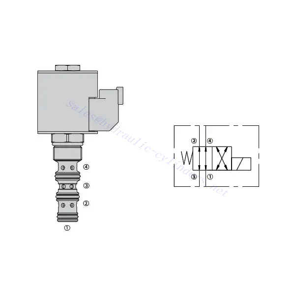
30SD10-40 Solenoid Directional Valve
The 30SD10-40 solenoid directional valve is a high-performance industrial component designed to deliver precise and reliable fluid control in a variety of applications. With its advanced features, durable construction, and user-friendly design, this solenoid directional valve offers enhanced efficiency and operational reliability.
The 30SD10-40 solenoid directional valve is a reliable and versatile component that offers precise fluid control in industrial applications. Its robust construction, precision control, and reliable performance enhance efficiency and productivity in fluid control systems. By following the recommended usage methods and maintenance guidelines, you can ensure optimal performance and longevity of the 30SD10-40 solenoid directional valve in your industrial operations.
30SD10-40 Solenoid Directional Valve Characteristics:
- Robust Construction: The 30SD10-40 solenoid directional valve is built with exceptional craftsmanship and high-quality materials, ensuring durability and longevity. Its sturdy construction allows it to withstand demanding industrial environments, providing reliable performance even in harsh conditions.
- Versatile Functionality: This solenoid directional valve offers versatile functionality, making it suitable for a wide range of applications. It effectively controls the direction of fluid flow, enabling precise and efficient operation in various industrial systems.
- Precision Control: The 30SD10-40 solenoid directional valve provides exceptional precision in fluid control. It allows for accurate regulation and adjustment of fluid direction and pressure, ensuring optimal performance and efficiency in industrial processes.
- Reliable Performance: This solenoid directional valve delivers reliable performance, minimizing the risk of system failures or interruptions. It operates with dependability, contributing to increased productivity and reduced downtime in industrial operations.
30SD10-40 Solenoid Directional Valve Parameter:
| 额定压力 | 207巴(3000磅/平方英寸) | |
| 峰值流量 | 23 L/min (6 gpm) | |
| 体液 | 矿物基或具有润滑性能的合成材料 | |
| Temperature range ℃ | -54 to 107 ℃ (Polyurethane seals) | |
| -40 至 100 ℃(丁腈橡胶密封圈) | ||
| -26 至 204 ℃(氟碳密封件) | ||
| 粘度范围 | 7.4至420毫米2/秒 | |
| 污染程度 | 最低污染等级为ISO4406 20/18/14级,建议使用17/15/13级以延长使用寿命 | |
| 内部泄漏 | ≤ 82 mL/min@207bar | |
| 腔体 | VC10-4 | |
| 线圈额定负载 | 额定电压从 85% 持续到 115% | |
| 20℃时线圈初始电流 | 电子线圈 | 12VDC 时为 1.7A;24VDC 时为 0.85A |
| D线圈 | 12VDC 时电流为 1.67A;24VDC 时电流为 0.83A | |
| 最小吸合电压 | 85% of nominal at 207 bar | |
30SD10-40 Solenoid Directional Valve Advantages:
• 额定连续工作线圈
• 墨盒电压可互换
• 可选防水 E 型线圈,防护等级高达 IP69K
• 高效的湿式电枢结构
• 行业通用腔体
• 硬化部件,使用寿命更长
Usage Method Of 30SD10-40 Solenoid Directional Valve :
- Integration into the System: Integrate the 30SD10-40 Solenoid Directional Valve into the fluid control system following the manufacturer’s guidelines and specifications. Ensure proper alignment and connection between the valve and other system components to achieve optimal performance.
- Electrical Connection: Establish a secure electrical connection for the solenoid directional valve. Follow the provided wiring diagram and ensure correct polarity to prevent electrical malfunctions. Adhere to safety guidelines when working with electrical connections.
- Fluid Flow Direction Control: Utilize the solenoid directional valve to control the direction of fluid flow. The valve is typically equipped with a lever or actuator for manual adjustment. Alternatively, it can be integrated into an automated control system for remote operation.
- Pressure Adjustment: Use the solenoid directional valve to regulate fluid pressure within the system. Adjust the valve’s settings to achieve the desired pressure levels for optimal performance and efficiency.
How To Read Hydraulic Valve Schematics?
Reading hydraulic valve schematics requires a basic understanding of hydraulic symbols and their meanings. Here are the steps to help you read hydraulic valve schematics:
- Familiarize Yourself With Hydraulic Symbols: Hydraulic schematics use graphical symbols to represent various components and functions. Common symbols include squares for valves, lines for pipes or hoses, arrows for flow direction, and circles for pressure or flow control devices. Make sure you understand the meaning of these symbols before proceeding.
- Identify The Valve Types: Look for the valve symbols in the schematic. Valves can be represented by squares with different shapes and orientations. For example, a square with a diagonal line represents a check valve, while a square with an arrow inside denotes a directional control valve.
- Determine The Valve Function: Each valve symbol indicates its specific function. Directional control valves determine the flow direction of hydraulic fluid, while pressure control valves regulate pressure levels. Flow control valves manage the rate of fluid flow, and check valves allow flow in one direction only.
- Observe The Valve Connections: Pay attention to the lines or arrows entering and exiting the valve symbol. These lines represent the hydraulic fluid flow paths. Arrows indicate the flow direction, and lines connecting valves and other components indicate the connections.
- Analyze The Valve Ositions: Some hydraulic valve schematics include symbols to illustrate the valve positions. These symbols typically depict the valve spool or lever in different positions, such as open, closed, or partially open. Understanding the valve positions helps you determine the flow paths and the state of the hydraulic system.
- Consider Additional Symbols And Annotations: Hydraulic schematics may include additional symbols and annotations to indicate pressure gauges, flow meters, filters, accumulators, or other components. Familiarize yourself with these symbols and their meanings to gain a comprehensive understanding of the system.
- Follow The Flow Paths: Trace the flow paths from the hydraulic power source through the various valves and components to the actuator or desired output. Understand how the valves interact with one another and how they control fluid flow, pressure, and direction to achieve the desired system operation.
- Refer To The Legend Or Key: The schematic should have a legend or key that explains the meaning of each symbol used in the diagram. If you encounter unfamiliar symbols or have doubts about their meaning, refer to the legend for clarification.
- Seek Additional Resources If Needed: If you need a more in-depth understanding of hydraulic valve schematics, consider referring to hydraulic textbooks, online resources, or consulting with hydraulic experts who can provide guidance and explanations tailored to your specific needs.
工厂的能力和产能:
(1) 装配
我们拥有一流的自主研发装配平台。液压油缸生产车间拥有 4 条半自动提升油缸装配线和 1 条全自动倾斜油缸装配线,设计年生产能力 100 万支。特种油缸车间配备了各种规格的半自动清洗装配系统,设计年生产能力 20 万只,并配备了知名数控加工设备、加工中心、高精度油缸加工专用设备、机器人焊接机、自动清洗机、油缸自动装配机、自动喷漆生产线等。现有关键设备 300 多台(套)。设备资源的优化配置和高效利用,保证了产品的精度要求,满足了产品的高质量需求。


(2) 机加工
加工车间配备了定制的斜轨车削中心、加工中心、高速珩磨机、焊接机器人及其他相关设备,可加工最大内径 400 毫米、最大长度 6 米的气缸管。

(3) 焊接

(4) 油漆和涂料
配备中小型圆筒自动水性漆喷涂线,实现机器人自动上下料和自动喷涂,设计产能为每班 4000 件;
我们还拥有一条由动力链驱动的大型油缸半自动喷漆生产线,设计产能为每班 60 箱。


(5) 测试
我们拥有一流的检验设施和试验台,确保气缸的性能符合要求。

我们是最好的液压缸制造商之一。我们能够提供全面的液压缸。我们还提供相应的 农用齿轮箱凭借卓越的产品质量和售后服务,我们的产品远销世界各地,赢得了良好的声誉。我们欢迎国内外客户与我们联系洽谈业务、交流信息,并 与我们合作!
液压缸应用:
