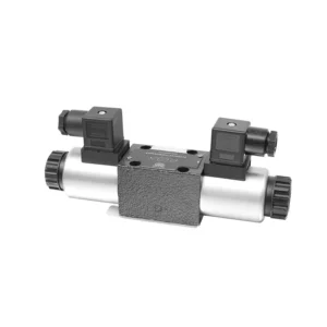
4WRA(E) Series Direct operated Proportional Directional Hydraulic Valve

作为液压缸制造商、供应商和机械产品出口商之一,我们提供液压缸和许多其他产品。

详情请与我们联系。

邮件sales@hydraulic-cylinders.net

液压缸制造商、供应商和出口商。

4WRA(E) Series Direct operated Proportional Directional Hydraulic Valve

The 4WRA(E) series direct operated proportional directional hydraulic valve is a state-of-the-art hydraulic component designed to provide precise control and efficient operation in hydraulic systems. With its direct-operated proportional directional control technology, this valve offers accurate flow control, seamless direction changes, and optimized performance.

The 4WRA(E) series direct operated proportional directional hydraulic valve empowers hydraulic systems with precise flow control, versatile directional changes, and optimal energy efficiency. Its direct-operated proportional control technology ensures accurate and responsive operation, while the high flow capacity and energy-efficient design contribute to enhanced system performance. By following the recommended usage methods and maintenance guidelines, you can maximize the benefits and longevity of the 4WRA(E) series valve, elevating your hydraulic system to new levels of precision and efficiency. Upgrade your hydraulic setup today and experience the power of the 4WRA(E) series direct operated proportional directional hydraulic valve.

4WRA(E) Series Direct operated Proportional Directional Hydraulic Valve Key Characteristics:

  • Direct Operated Proportional Control:
    • The 4WRA(E) series valve utilizes direct-operated proportional control, allowing for precise and immediate response to control signals.
    • This feature ensures accurate flow control and seamless transitions between different hydraulic functions.
  • High Flow Capacity:
    • With its robust design, the valve offers high flow capacity, making it suitable for applications requiring substantial hydraulic power.
    • It allows for efficient handling of large fluid volumes, contributing to enhanced system performance.
  • Versatile Directional Control:
    • The 4WRA(E) series valve provides versatile directional control, enabling smooth and precise changes in hydraulic fluid direction.
    • It allows for the seamless activation of hydraulic components such as cylinders, motors, and actuators in different directions.
  • Energy Efficiency:
    • Designed with energy efficiency in mind, this valve minimizes pressure drops and optimizes flow control, resulting in reduced energy consumption.
    • By efficiently managing hydraulic power, it helps maximize system performance while minimizing operational costs.

4WRA(E) Series Direct operated Proportional Directional Hydraulic Valve Parameter:

Hydraulic
Installation positionoptional, preferably horizontal
Size610
Weight4WRA…L2XKg26.6
4WRAE…L2X2.26.8
Rated flow qnom,when Δp = 10 barL/min7、15、2630、60
Hysteresis%≤5
Repeatability%≤1
Response sensitivity%≤0.5
Max. operating  pressurePort s A B Pbar315
Port  Tbar210
 FluidMineral oil suitable for NBR and FKM seal
Phosphate ester for FKM seal
 Fluid temperature range4WRA…L2X-20℃ to 70℃(-4°F to 158°F)
4WRAE…L2X-20℃ to 50℃(-4° F to 122° F)
 Viscosity range mm²/s20 to 380(preferably 30 to 46)
 Degree of contaminationNAS1638 class9 or ISO 4406 class 20/18/15
Electrical data
1)solenoid
Voltage typeDC
Command value signal±10V or 4~20mA
Max. current per solenoidA2.51.50.8
Coil resistance Cold valueΩ24.819.5
 Max. warm value37.228.8
Duty%ED100%
Coil temperature150
Valve protection to EN 60529IP 65
2)Control electronics
Ampilfier4WRA…L2XVT-VSPA2-L2X
4WRAE…L2XIntegrated in the valve(OBE)
Operating voltageNominal voltageVDC24
Lower limiting valueV21/22(4WRA),19(4WRAE)
Upper limiting valueV35
Amplifier current consumptionImaxA<1.8
ImaxA3

4WRA(E) Series Direct operated Proportional Directional Hydraulic Valve Advantages:

• Direct-acting proportional directional valve, used to control the flow and direction of liquid flow
• Panel type installation
• The proportional solenoid actuates the valve core through the threaded connection, and the coil can be removed separately
• Spool spring alignment alignment
• Optional with built-in amplifier, 4WRAE…L2X type input can be A1 or F1
• Supporting supply of external amplifier

Usage Method Of 4WRA(E) Series Direct operated Proportional Directional Hydraulic Valve:

  • System Evaluation:
    • Evaluate your hydraulic system and identify the specific flow control and directional requirements.
    • Determine if the 4WRA(E) series valve is suitable based on its flow capacity, pressure rating, and compatibility with your system.
  • Valve Selection:
    • Select the appropriate variant of the 4WRA(E) series valve based on your system parameters, flow requirements, and directional control needs.
    • Consider factors such as maximum flow rate, pressure rating, response time, and operational conditions.
  • Installation:
    • Follow the manufacturer’s installation instructions carefully, ensuring proper alignment and secure valve mounting.
    • Connect the valve to the hydraulic system, ensuring leak-free connections and proper flow direction alignment.
  • Control Signal Connection:
    • Connect the control signal wires of the valve to the appropriate control device, such as a proportional amplifier or electronic control unit.
    • Ensure proper wiring and compatibility between the valve and the control device to enable accurate and responsive control.

How To Adjust Valve Lash On Hydraulic Lifters?

Adjusting valve lash on hydraulic lifters is a crucial maintenance task to ensure proper engine performance and prevent issues such as noisy valves or reduced power. Here’s a step-by-step guide on how to adjust valve lash on hydraulic lifters:

  1. Preparation:
    • Ensure the engine is off and cool before starting the adjustment process.
    • Familiarize yourself with the engine’s firing order and the specific valve lash specifications provided by the manufacturer for your engine model.
  2. Identify the Correct Cylinder:
    • Locate the firing position of the engine by referring to the engine’s firing order diagram.
    • Identify the cylinder that corresponds to the specific valve you want to adjust.
  3. Position the Cylinder:
    • Rotate the engine crankshaft manually using a socket wrench or the engine’s built-in turning mechanism.
    • Position the cylinder you want to adjust at the top dead center (TDC) on the compression stroke. You can do this by aligning the timing marks on the crankshaft pulley or using a piston stop tool.
  4. Loosen the Rocker Arm:
    • Locate the rocker arm on the specific valve you want to adjust.
    • Loosen the rocker arm nut or adjuster screw using an appropriate wrench or socket.
  5. Adjust the Valve Lash:
    • With the rocker arm loose, you can now adjust the valve lash. The valve lash is the clearance between the rocker arm and the valve stem.
    • Use a feeler gauge to measure the existing valve lash. Insert the appropriate thickness gauge between the rocker arm and the valve stem.
    • If the clearance is too tight, meaning the feeler gauge does not fit or has excessive resistance, you need to increase the valve lash. If the clearance is too loose, meaning the feeler gauge slides in too easily, you need to decrease the valve lash.
    • To adjust the valve lash, tighten or loosen the rocker arm nut or adjuster screw accordingly. Refer to the manufacturer’s specifications for the recommended amount of adjustment to be made.
  6. Recheck the Valve Lash:
    • After making the adjustment, recheck the valve lash using the feeler gauge to ensure it falls within the recommended specifications.
    • Repeat the adjustment process if necessary until the correct valve lash is achieved.
  7. Repeat for Other Cylinders:
    • Proceed to the next cylinder in the firing order and repeat steps 4 to 6 for each cylinder you want to adjust.
    • Remember to rotate the crankshaft and position each cylinder at TDC on the compression stroke before adjusting its valve lash.
  8. Secure the Rocker Arm:
    • Once the valve lash is properly adjusted for each cylinder, tighten the rocker arm nut or adjuster screw to the manufacturer’s recommended torque specification.
    • Double-check that the valve lash remains within the specified range after tightening.
  9. Final Checks:
    • Rotate the engine crankshaft a few times to ensure smooth rotation and check for any unusual noises or resistance.
    • Start the engine and listen for any abnormal valve noises. If you hear excessive tapping or knocking, recheck the valve lash adjustment.

工厂的能力和产能:

(1) 装配

我们拥有一流的自主研发装配平台。液压油缸生产车间拥有 4 条半自动提升油缸装配线和 1 条全自动倾斜油缸装配线,设计年生产能力 100 万支。特种油缸车间配备了各种规格的半自动清洗装配系统,设计年生产能力 20 万只,并配备了知名数控加工设备、加工中心、高精度油缸加工专用设备、机器人焊接机、自动清洗机、油缸自动装配机、自动喷漆生产线等。现有关键设备 300 多台(套)。设备资源的优化配置和高效利用,保证了产品的精度要求,满足了产品的高质量需求。

(2) 机加工

加工车间配备了定制的斜轨车削中心、加工中心、高速珩磨机、焊接机器人及其他相关设备,可加工最大内径 400 毫米、最大长度 6 米的气缸管。

(3) 焊接

(4) 油漆和涂料

配备中小型圆筒自动水性漆喷涂线,实现机器人自动上下料和自动喷涂,设计产能为每班 4000 件;
我们还拥有一条由动力链驱动的大型油缸半自动喷漆生产线,设计产能为每班 60 箱。

(5) 测试

我们拥有一流的检验设施和试验台,确保气缸的性能符合要求。


We are one of the best hydraulic cylinder manufacturers. We can offer comprehensive hydraulic cylinders. We also provide corresponding 农用齿轮箱. We have exported our products to clients worldwide and earned a good reputation because of our superior product quality and after-sales service. We welcome customers at home and abroad to contact us to negotiate business, exchange information, and 与我们合作!


参观我们的 VR 工厂

通过以下方式参观我们的 VR 工厂

叉车液压缸如何工作?

液压缸应用:

液压缸的两种基本类型和工作原理:

    zh_CNZH