
4WRKE Series Pilot Operated Proportional Directional Hydraulic Valve
4WRKE Series Pilot Operated Proportional Directional Hydraulic Valve
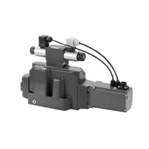
The 4WRKE series pilot-operated proportional directional hydraulic valve is a cutting-edge hydraulic component designed to provide superior precision, control, and efficiency in hydraulic systems. With its advanced pilot-operated proportional control technology, this valve enables accurate flow regulation and seamless directional changes.
The 4WRKE series pilot-operated proportional directional hydraulic valve empowers hydraulic systems with precise flow control, versatile directional changes, and energy efficiency. Its pilot-operated proportional control technology ensures accurate and responsive flow adjustment, while the high flow capacity guarantees reliable performance even in demanding applications. By following the recommended usage methods and maintenance guidelines, you can maximize the benefits and longevity of the 4WRKE series valve, elevating your hydraulic system to new levels of precision and control. Upgrade your hydraulic setup today and experience the power of the 4wrke series pilot-operated proportional directional hydraulic valve.
4WRKE Series Pilot Operated Proportional Directional Hydraulic Valve Key Characteristics:
- 先导操作比例控制
- The 4WRKE series valve utilizes pilot-operated proportional control technology, allowing precise and proportional flow adjustment based on control signals.
- 该功能可确保精确、灵敏的控制,从而提高系统性能、降低能耗并提高生产效率。
- 多功能方向控制
- 该阀门可灵活控制液压流体方向,适用于多种应用。
- 它能够无缝地激活和停用液压元件(如油缸、马达和执行器)的不同方向,从而增强系统的灵活性和适应性。
- 高流量容量
- The 4WRKE series valve is engineered to handle high flow rates, making it ideal for applications that require substantial hydraulic power.
- 其坚固的结构确保即使在苛刻的条件下也能可靠运行,提供稳定高效的流量控制。
- 能源效率
- 通过采用先导式比例控制,该阀门可最大限度地减少压力损失并优化能源利用。
- 它有助于降低能源消耗,从而节省成本并带来环境效益。
4WRKE Series Pilot Operated Proportional Directional Hydraulic Valve Parameter:
| 一般的 | |||||||||
| 尺寸 | 10 | 16 | 25 | 27 | 32 | 35 | |||
| Installation and commissioning guidelines | 可选,最好是水平的 | ||||||||
| 存储温度范围 | ℃ | – 20 to + 80 | |||||||
| 环境温度范围 | ℃ | -20 to + 50 | |||||||
| 重量 | 公斤 | 8.7 | 11.2 | 16.8 | 20 | 37.2 | 72 | ||
| 液压 ( measured at p=100bar,with HLP46 at ϑoil =40℃ ±5℃) | |||||||||
| 工作压力 | -Pilot control valve | Pilot oil supply | 酒吧 | 25 to 315 | |||||
| -Main valve | Port P A B | 酒吧 | Up to 315 | Up to 350 | Up to 350 | Up to 210 | Up to 350 | Up to 350 | |
| 回压 | T 端口
(Pilot oil drain) |
Internal | 酒吧 | Static < 10 | |||||
| External | 酒吧 | Up to 315 | Up to 250 | Up to 250 | Up to 210 | Up to 250 | Up to 250 | ||
| Y端口 | 酒吧 | Static < 10 | |||||||
| Nominal flow qVnom ±10% at Δp=10bar (Δp = valve pressure differential) |
升/分钟 | 25 50 | – 125 | – 220 | – – | – 440 | – | ||
| 100 | 180 | 350 | 500 | 600 | 1000 | ||||
| Flow of main valve (max. permissible) | 升/分钟 | 170 | 460 | 870 | 1000 | 1600 | 3000 | ||
| Pilot oil flow at port X or Y with a step form of input signal from 0 to 100 % (315 bar) | 升/分钟 | 4.1 | 8.5 | 11.7 | 11.7 | 13 | 13 | ||
| 压力流体 | Mineral oil(HL,HLP)to DIN 51 524 Phosphate ester (HFD-R) | ||||||||
| 流体温度范围 | ℃ | 10 to 80, preferably 40 to 50 | |||||||
| 粘度范围 | 毫米2/秒 | 20 to 380, preferably 30 to 45 | |||||||
| 污染程度 | Maximum permissible degree of contamination: NAS 1638. | A filter with a minimum retention rate of βx = 75 is recommended | |||||||
| Pilot control valve | Class 7 | x = 5 | |||||||
| 主阀 | Class 9 | x = 7 | |||||||
| 滞后 | % | ≤1 | |||||||
| 反应敏感度 | % | ≤0.5 | |||||||
| 电气 | |||||||||
| 电压类型 | 直流 | ||||||||
| 电气连接 | Plug-in connector to DIN EN175 201-804 | ||||||||
| Power, max. | W | 72 (average = 24W) | |||||||
| 控制电子设备 | Integrated into the valve | ||||||||
4WRKE Series Pilot Operated Proportional Directional Hydraulic Valve Advantages:
• Pilot-operated two-stage proportional directional valve with electrical position feedback of the main spool, used to control the size and direction of the liquid flow
• Sub-plate mounting type connection structure, connection size conforms to ISO 4401 standard
• Spring centred main spool
• With integrated proportional amplifier
• The pilot control is a single-stage proportional directional valve
• The pilot valve is a threaded proportional solenoid, and the coil can be disassembled separately
Usage Method Of 4WRKE Series Pilot Operated Proportional Directional Hydraulic Valve:
- 系统评估
- 评估您的液压系统,并确定具体的流量和方向控制要求。
- Determine if the 4WRKE Series Valve is suitable based on its flow capacity, pressure rating, and compatibility with your system.
- 阀门选择
- Select the appropriate variant of the 4WRKE Series Valve based on your system parameters, flow requirements, and directional control needs.
- 考虑最大流量、压力等级、响应时间和操作条件等因素。
- 安装
- 请仔细按照制造商的安装说明进行操作,确保阀门正确对准并牢固安装。
- 确保连接处无泄漏,并保证正确的流向对齐,以保证最佳性能。
- 控制信号连接
- 将阀门的控制信号线连接到合适的控制装置,例如比例放大器或电子控制单元。
- 确保阀门与控制装置之间接线正确且兼容,以实现精确、灵敏的控制。
How To Clean Hydraulic Valve Lifters?
Cleaning hydraulic valve lifters is an important maintenance task that helps ensure proper engine performance and reduce noise caused by dirt or debris buildup. Here’s a step-by-step guide on how to clean hydraulic valve lifters:
- 准备必要的工具和材料:
- New engine oil
- 干净的抹布或毛巾
- Engine degreaser or parts cleaner
- Small brush or toothbrush
- Plastic container or tray
- 准备:
- Allow the engine to cool down completely before starting the cleaning process.
- Remove the valve cover or covers to access the hydraulic valve lifters. Refer to the manufacturer’s instructions or a repair manual for your specific engine to locate and remove the valve cover(s) properly.
- Removal of Hydraulic Valve Lifters:
- Identify the hydraulic valve lifters in the engine.
- One at a time, carefully remove the hydraulic valve lifters from their respective locations. Depending on your engine, you may need to remove other components or parts to access the lifters.
- Place each lifter in a plastic container or tray in the order they were removed. This will help ensure they are reinstalled correctly later.
- Cleaning the Lifters:
- Pour a small amount of engine degreaser or parts cleaner into a container.
- Place one hydraulic valve lifter into the container, ensuring it is fully submerged in the cleaner.
- Allow the lifter to soak for the recommended duration specified by the cleaner manufacturer. This usually ranges from 15 minutes to an hour.
- Use a small brush or toothbrush to gently scrub the lifter’s exterior surfaces, removing any deposits or dirt.
- Rinse the lifter thoroughly with clean water to remove any remaining cleaner or debris.
- Dry the lifter using a clean rag or towel. Ensure there are no traces of moisture before reinstallation.
- Reinstallation:
- Apply a small amount of fresh engine oil to the cleaned lifter’s exterior surface.
- Carefully place the lifter back into its original position in the engine, ensuring it is properly aligned and seated.
- Repeat the cleaning process for each hydraulic valve lifter, following the same steps.
- Once all the lifters are cleaned and reinstalled, make sure they are secured properly.
- 重新组装:
- Reinstall the valve cover(s) according to the manufacturer’s instructions.
- Double-check that all components and parts are properly secured and tightened.
- Test and Inspection:
- Start the engine and let it run for a few minutes to ensure proper operation and to allow the lifters to refill with oil.
- Listen for any abnormal noises or ticking sounds that could indicate further issues.
- If noise or performance problems persist, it may be necessary to consult a professional mechanic for further diagnosis and repair.
工厂的能力和产能:
(1) 装配
我们拥有一流的自主研发装配平台。液压油缸生产车间拥有 4 条半自动提升油缸装配线和 1 条全自动倾斜油缸装配线,设计年生产能力 100 万支。特种油缸车间配备了各种规格的半自动清洗装配系统,设计年生产能力 20 万只,并配备了知名数控加工设备、加工中心、高精度油缸加工专用设备、机器人焊接机、自动清洗机、油缸自动装配机、自动喷漆生产线等。现有关键设备 300 多台(套)。设备资源的优化配置和高效利用,保证了产品的精度要求,满足了产品的高质量需求。


(2) 机加工
加工车间配备了定制的斜轨车削中心、加工中心、高速珩磨机、焊接机器人及其他相关设备,可加工最大内径 400 毫米、最大长度 6 米的气缸管。

(3) 焊接

(4) 油漆和涂料
配备中小型圆筒自动水性漆喷涂线,实现机器人自动上下料和自动喷涂,设计产能为每班 4000 件;
我们还拥有一条由动力链驱动的大型油缸半自动喷漆生产线,设计产能为每班 60 箱。


(5) 测试
我们拥有一流的检验设施和试验台,确保气缸的性能符合要求。

我们是最好的液压缸制造商之一。我们能够提供全面的液压缸。我们还提供相应的 农用齿轮箱凭借卓越的产品质量和售后服务,我们的产品远销世界各地,赢得了良好的声誉。我们欢迎国内外客户与我们联系洽谈业务、交流信息,并 与我们合作!
液压缸应用:
