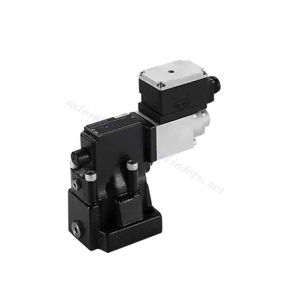
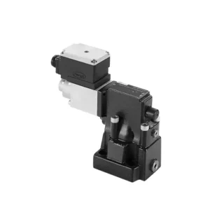
DBE/M(E) Series Proportional Pressure Relief Hydraulic Valve

作为液压缸制造商、供应商和机械产品出口商之一,我们提供液压缸和许多其他产品。

详情请与我们联系。

邮件sales@hydraulic-cylinders.net

液压缸制造商、供应商和出口商。

DBE/M(E) Series Proportional Pressure Relief Hydraulic Valve

The DBE/M(E) series proportional pressure relief hydraulic valve is a state-of-the-art component designed to deliver precise pressure control in hydraulic systems. With its advanced proportional control technology, this valve ensures optimal performance, efficiency, and safety.

The DBE/M(E) series proportional pressure relief hydraulic valve empowers hydraulic systems with precise pressure control, enhanced efficiency, and equipment protection. With its advanced proportional control technology, this valve ensures optimal performance across various applications. By following the recommended usage methods and maintenance guidelines, you can maximize the benefits and reliability of the DBE/M(E) series valve, elevating the pressure control and overall performance of your hydraulic system. Upgrade your hydraulic setup today and experience superior pressure regulation with the DBE/M(E) series proportional pressure relief hydraulic valve.

DBE6X(E) Series Proportional Pressure Relief Hydraulic Valve Key Characteristics:

  • Proportional Pressure Relief:
    • The DBE/M(E) series valve offers precise and proportional pressure relief, allowing for dynamic control of hydraulic pressure.
    • It ensures accurate pressure regulation in response to varying load conditions, preventing system overload and safeguarding hydraulic components.
  • Enhanced System Efficiency:
    • This valve enables precise hydraulic pressure control, resulting in enhanced system efficiency and reduced energy consumption.
    • By maintaining the desired pressure levels, it minimizes pressure fluctuations, optimizes system performance, and reduces operational costs.
  • Safety and Equipment Protection:
    • The DBE/M(E) series valve acts as a protective mechanism by limiting the pressure within the hydraulic system, safeguarding equipment and operators.
    • It prevents excessive pressure build-up, reducing the risk of component damage, system failures, and potential accidents.
  • Proportional Control Functionality:
    • With its proportional control technology, the DBE/M(E) series valve offers smooth and precise pressure adjustment.
    • It allows for real-time pressure control, enabling seamless integration into various hydraulic systems and applications.

DBE/M(E) Series Proportional Pressure Relief Hydraulic Valve Parameter:

General
FluidMineral oil suitable for NBR and FKM seal
Phosphate ester for FKM seal
Fluid temperature range-30  to +80 (NBR seals)
-20 to +80 (FKM seals)
Viscosity rangemm2/s2.8   to 380
Degree of contaminationMaximum permissible degree of fluid contamination: Class 9. NAS 1638 or 20/18/15, ISO4406
Max. operating  pressure315 bar
Port A、B、Xbar50; 100; 200; 315
Max. setting pressurebarIn relation to Flow (Q), see characteristic curves
Min. settable pressure=Min. settable pressure
Min. settable pressure at 0 command valueSeparate and at zero pressure to tanks
Return oil pressure port Y barSetting pressurePressure range under Max.  safety pressure
Max. pressure safety (infinitely adjustable)50 bar10-60+20 bar
100 bar10-120+20 bar
200 bar10-220+20 bar
315 bar10-340+20 bar
Max. pressure safety setting conditionWhen rated pressure is 50 bar, between 60 bar and 80 bar
When rated pressure is 100 bar, between120 bar and 140 bar
When rated pressure is 200 bar, between 220 bar and 240 bar
When rated pressure is 315 bar, between 340 bar and 360 bar
Size102532
Max. flow-rate200400600
Pilot oil (for pilot valve))L/min0.7  to 2
LinearityL/min±3.5%
Repeatability<±2%
Hysteresiswith shimmywithout shimmy
±1.5% P max        (200Hz, amplitude 200mAsss)±4.5% P max
Switching time30~150ms(independent with the system)
Electrical data
PowerDC
Min. solenoid currentmA100
Max. solenoid currentmA800
Coil resistance19.5Ω at 20℃, Max. warm value: 28.8Ω
Working statusContinuous
Max. Ambient temperature range+50℃
Electrical connectionPlug-in connector to DIN 43 650/2 +SL/PG11
Insulation to DIN 40 050IP 65
AmplifierVT2000

DBE/M(E) Series Proportional Pressure Relief Hydraulic Valve Advantages:

• Used for bottom sub-plate mounting
• Installation face follow DIN24340 E and ISO 6264
• Used in oil path block installation
• Four pressure ranges
• Highest pressure protection structure (optional)
• Matching electronic amplifier VT-2000 type (must be ordered separately)

Usage Method Of DBE/M(E) Series Proportional Pressure Relief Hydraulic Valve:

  • System Evaluation:
    • Evaluate your hydraulic system and identify the specific pressure control requirements.
    • Determine if the DBE/M(E) series valve is compatible with your system based on its pressure range, flow capacity, and other specifications.
  • Valve Selection:
    • Choose the appropriate DBE/M(E) series valve variant based on your system parameters, pressure range, and flow requirements.
    • Consider maximum pressure rating, response time, and operational conditions.
  • Installation:
    • Follow the manufacturer’s installation instructions carefully, ensuring proper alignment and secure valve mounting.
    • Connect the valve to the hydraulic system, ensuring leak-free connections and proper flow direction alignment.
  • Pressure Adjustment:
    • Utilize the proportional control signal or adjustment mechanism provided with the DBE/M(E) series valve to set the desired pressure relief level.
    • Adjust the valve incrementally, monitoring the pressure gauge readings and system response to achieve precise pressure control.

How To Adjust Hydraulic Pressure Relief Valve?

Adjusting a hydraulic pressure relief valve allows you to regulate the maximum pressure within a hydraulic system. This is important for maintaining system integrity and preventing damage to components. Here’s a step-by-step guide on how to adjust a hydraulic pressure relief valve:

  1. Identify the Pressure Relief Valve:
    • Locate the hydraulic pressure relief valve in your system. It is typically positioned in the hydraulic line or integrated into a manifold block.
  2. Understand the Valve Design:
    • Familiarize yourself with the specific design of the pressure relief valve you are working with. Different valves may have varying adjustment mechanisms, such as a knob, screw, or locknut.
  3. Determine the Desired Pressure Setting:
    • Assess the requirements of your hydraulic system and determine the desired maximum pressure. Consider the system’s specifications, load conditions, and safety limits.
  4. Prepare the System:
    • Before making any adjustments, shut off the hydraulic system and relieve the pressure by moving the control levers back and forth or following the manufacturer’s recommended procedure.
  5. Locate the Adjustment Mechanism:
    • Identify the adjustment mechanism on the pressure relief valve. It could be a knob, screw, or locknut positioned on the valve body or adjacent to it.
  6. Adjust the Valve:
    • If the valve has a knob or handle, turn it clockwise to increase the pressure relief setting or counterclockwise to decrease it. If the valve has a screw, turn it clockwise to increase the ground or counterclockwise to drop it.
  7. Make Incremental Adjustments:
    • When adjusting the pressure relief valve, make small, incremental changes to avoid sudden or drastic variations in pressure. This allows you to fine-tune the system and prevent potential damage.
  8. Observe the System:
    • With each adjustment, observe the hydraulic system’s pressure gauge or indicator to see the effect of the changes. Ensure that the pressure stays within the desired range.
  9. Test and Verify:
    • Gradually increase the system’s pressure and monitor the pressure relief valve’s response. Ensure it relieves stress when the maximum set pressure is reached and maintains the desired maximum pressure.
  10. Lock the Adjustment:
    • Once you have achieved the desired pressure setting, secure the adjustment mechanism to prevent unintended changes. Some valves may have a locking nut or set screw that can be tightened to hold the adjustment in place.
  11. Document the Adjustment:
    • Keep a record of the adjusted pressure relief setting for future reference and maintenance purposes. This documentation will help maintain consistency and aid troubleshooting efforts.

工厂的能力和产能:

(1) 装配

我们拥有一流的自主研发装配平台。液压油缸生产车间拥有 4 条半自动提升油缸装配线和 1 条全自动倾斜油缸装配线,设计年生产能力 100 万支。特种油缸车间配备了各种规格的半自动清洗装配系统,设计年生产能力 20 万只,并配备了知名数控加工设备、加工中心、高精度油缸加工专用设备、机器人焊接机、自动清洗机、油缸自动装配机、自动喷漆生产线等。现有关键设备 300 多台(套)。设备资源的优化配置和高效利用,保证了产品的精度要求,满足了产品的高质量需求。

(2) 机加工

加工车间配备了定制的斜轨车削中心、加工中心、高速珩磨机、焊接机器人及其他相关设备,可加工最大内径 400 毫米、最大长度 6 米的气缸管。

(3) 焊接

(4) 油漆和涂料

配备中小型圆筒自动水性漆喷涂线,实现机器人自动上下料和自动喷涂,设计产能为每班 4000 件;
我们还拥有一条由动力链驱动的大型油缸半自动喷漆生产线,设计产能为每班 60 箱。

(5) 测试

我们拥有一流的检验设施和试验台,确保气缸的性能符合要求。


We are one of the best hydraulic cylinder manufacturers. We can offer comprehensive hydraulic cylinders. We also provide corresponding 农用齿轮箱. We have exported our products to clients worldwide and earned a good reputation because of our superior product quality and after-sales service. We welcome customers at home and abroad to contact us to negotiate business, exchange information, and 与我们合作!


参观我们的 VR 工厂

通过以下方式参观我们的 VR 工厂

叉车液压缸如何工作?

液压缸应用:

液压缸的两种基本类型和工作原理:

    zh_CNZH