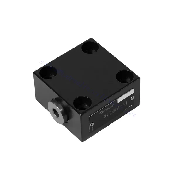
L-LFA系列方向控制液压阀
L-LFA系列方向控制液压阀
The L-LFA series directional control hydraulic valve is a cutting-edge component designed to deliver precise control and optimal performance in hydraulic systems. With its advanced features and robust construction, this valve provides reliable and efficient directional control for various applications.
The L-LFA series directional control hydraulic valve is a game-changer for hydraulic systems, offering precise directional control, versatility, and durability. By following the recommended usage methods and maintenance guidelines, you can harness the full potential of the L-LFA series valve and experience enhanced control, efficiency, and productivity in your hydraulic applications. Upgrade your hydraulic system today and unlock the advantages of precision and efficiency with the L-LFA series directional control hydraulic valve.
L-LFA Series Directional Control Hydraulic Valve Key Characteristics:
- Accurate Directional Control:
- The L-LFA series valve offers exceptional directional control, allowing precise and efficient management of fluid flow in hydraulic systems.
- This characteristic enables operators to direct hydraulic fluid to specific actuators or hydraulic components, facilitating smooth and controlled movement.
- Versatile Configuration Options:
- This valve is available in various configurations, including 2-way, 3-way, and 4-way options, ensuring compatibility with diverse hydraulic system requirements.
- The 2-way configuration facilitates simple on/off control, while the 3-way and 4-way configurations enable more complex functions such as cylinder extension, retraction, and bi-directional control.
- High-Performance Construction:
- The L-LFA series valve is engineered with high-quality materials and precision manufacturing techniques to ensure durability and longevity.
- Its robust construction allows it to withstand high pressures, temperature variations, and harsh operating conditions, ensuring reliable performance even in demanding environments.
- 快速响应时间:
- This valve boasts an impressive response time, enabling rapid and efficient fluid flow control within the hydraulic system.
- The quick response time facilitates precise and immediate adjustments, resulting in enhanced system performance and reduced energy consumption.
L-LFA Series Directional Control Hydraulic Valve Parameter:
| Maximum working pressure | Without directional valve | 酒吧 | 420 | |||||
| – Oil port A、B、X、Z1、Z2 | 酒吧 | 315; 350; 420(Depends on top-mounted directional valve) | ||||||
| – Oil port Y | 酒吧 | Equivalent to the return pressure of a top-mounted directional valve | ||||||
| 体液 | 适用于 NBR 和 FKM 密封件的矿物油 | |||||||
| FKM密封用磷酸酯 | ||||||||
| 流体温度范围 | ℃ | -30 至 +80(丁腈橡胶密封) | ||||||
| -20 至 +80(FKM 密封圈) | ||||||||
| 粘度范围 | 毫米2/秒 | 2.8 to 380 | ||||||
| 污染程度 | 流体污染最大允许程度:9 级。符合 NAS 1638 或 20/18/15、ISO 4406 标准。 | |||||||
L-LFA Series Directional Control Hydraulic Valve Advantages:
• Basic type D with remote control
• With stroke limiter H
• Built-in shuttle valve G
• Built-in directional seat valve R, RF
• Can be equipped with directional valve WE
Usage Method Of L-LFA Series Directional Control Hydraulic Valve:
- 系统评估:
- Evaluate your hydraulic system and identify the specific directional control requirements.
- Determine whether the L-LFA series valve suits your system based on flow rates, pressure ratings, and compatibility with your application.
- 阀门选择:
- Select the appropriate variant of the L-LFA series valve based on your system parameters and directional control needs.
- Consider factors such as valve type (2-way, 3-way, or 4-way), flow capacity, pressure rating, and compatibility with your specific application.
- 安装:
- Follow the manufacturer’s installation instructions carefully to ensure proper alignment and secure valve mounting.
- Use compatible hydraulic fittings, adapters, and seals to establish leak-free connections. Tighten the connections adequately, avoiding overtightening that could damage the valve or fittings.
- 系统集成:
- Connect the hydraulic lines to the appropriate ports of the L-LFA series valve, ensuring the correct flow direction.
- Verify that the valve is installed in the correct orientation, as indicated by the directional arrows on the valve body.
- 操作和控制:
- Familiarize yourself with the control mechanisms of the L-LFA Series Valve, such as levers, knobs, or solenoids.
- Ensure that the valve is actuated correctly and that the desired hydraulic flow is achieved based on the system requirements.
How To Install A Hydraulic Pressure Relief Valve?
Installing a hydraulic pressure relief valve is a crucial step in ensuring the safety and proper functioning of a hydraulic system. Here’s a step-by-step guide on how to install a hydraulic pressure relief valve:
- Identify the Valve: Determine the specific type and model of the hydraulic pressure relief valve you work with. Ensure it is suitable for your application and compatible with your hydraulic system requirements.
- Gather the Required Tools and Materials: Collect the necessary tools and materials, including appropriate hydraulic fittings, adapters, wrenches, Teflon tape (thread sealant), and a pressure gauge if needed. Refer to the manufacturer’s instructions for any specific tools or components required.
- 准备液压系统: Shut down the hydraulic system and relieve pressure by activating the relief valve or retracting hydraulic cylinders. This step is crucial for safety and prevents accidental movement or hydraulic fluid release.
- Identify the Pressure Relief Point: Determine the optimal location to install the hydraulic pressure relief valve in your hydraulic system. It should be positioned downstream of the pump before any sensitive components to protect them from excessive pressure. Consult the hydraulic system schematic or seek professional advice if necessary.
- 安装阀门: Securely mount the hydraulic pressure relief valve in the chosen location using appropriate brackets or clamps. Ensure the valve is positioned correctly, aligning the inlet and outlet ports with the flow direction. Follow the manufacturer’s instructions for specific mounting requirements.
- 连接进水口和出水口: Attach hydraulic hoses or tubing to the inlet and outlet ports of the relief valve. Use suitable hydraulic fittings and adapters to create a leak-free connection. Apply Teflon tape or thread sealant to the male threads of the fittings to ensure a secure and sealed connection. Tighten the connections using wrenches to avoid leaks, but be careful not to overtighten.
- Set the Pressure Relief Setting: Most hydraulic pressure relief valves come with an adjustable pressure relief setting. Adjust the relief valve to the desired pressure relief point using the manufacturer’s guidelines. Some valves may require a pressure gauge to accurately set the relief pressure. Install the pressure gauge temporarily, if needed, and adjust the relief valve until the desired pressure is achieved.
- 测试系统: Once the hydraulic pressure relief valve is installed, slowly restore hydraulic system pressure. Monitor the pressure gauge or observe the system behavior to ensure that the relief valve functions correctly. The relief valve should open and divert excess pressure when it reaches the set point, preventing damage to the system.
- Monitor and Maintain: Regularly inspect the hydraulic pressure relief valve for any signs of leakage, damage, or reduced performance. Clean the valve and surrounding area to remove dirt and debris that may affect its operation. Follow the manufacturer’s recommended maintenance schedule and guidelines to ensure optimal performance and longevity.
工厂的能力和产能:
(1) 装配
我们拥有一流的自主研发装配平台。液压油缸生产车间拥有 4 条半自动提升油缸装配线和 1 条全自动倾斜油缸装配线,设计年生产能力 100 万支。特种油缸车间配备了各种规格的半自动清洗装配系统,设计年生产能力 20 万只,并配备了知名数控加工设备、加工中心、高精度油缸加工专用设备、机器人焊接机、自动清洗机、油缸自动装配机、自动喷漆生产线等。现有关键设备 300 多台(套)。设备资源的优化配置和高效利用,保证了产品的精度要求,满足了产品的高质量需求。


(2) 机加工
加工车间配备了定制的斜轨车削中心、加工中心、高速珩磨机、焊接机器人及其他相关设备,可加工最大内径 400 毫米、最大长度 6 米的气缸管。

(3) 焊接

(4) 油漆和涂料
配备中小型圆筒自动水性漆喷涂线,实现机器人自动上下料和自动喷涂,设计产能为每班 4000 件;
我们还拥有一条由动力链驱动的大型油缸半自动喷漆生产线,设计产能为每班 60 箱。


(5) 测试
我们拥有一流的检验设施和试验台,确保气缸的性能符合要求。

我们是最好的液压缸制造商之一。我们能够提供全面的液压缸。我们还提供相应的 农用齿轮箱凭借卓越的产品质量和售后服务,我们的产品远销世界各地,赢得了良好的声誉。我们欢迎国内外客户与我们联系洽谈业务、交流信息,并 与我们合作!
液压缸应用:
