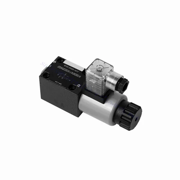
M-SED Series Directional Poppet Hydraulic Valve With Solenoid Actuation
M-SED Series Directional Poppet Hydraulic Valve With Solenoid Actuation
The M-SED series directional poppet hydraulic valve with solenoid actuation is a cutting-edge solution that provides precise control and optimal efficiency in hydraulic systems. With its innovative design, reliable performance, and advanced solenoid actuation, this valve offers enhanced fluid flow control, flexibility, and compatibility with various industrial applications.
The M-SED series directional poppet hydraulic valve with solenoid actuation is a reliable and efficient solution for hydraulic systems. With its directional poppet design, advanced solenoid actuation, versatility, and high flow capacity, this valve offers precise control, enhanced efficiency, and compatibility with various applications. The M-SED series valve delivers optimal performance and reliability by following the recommended usage methods and adhering to regular maintenance practices. Upgrade your hydraulic system with the M-SED series directional poppet hydraulic valve and experience enhanced control, efficiency, and productivity.
M-SED Series Directional Poppet Hydraulic Valve With Solenoid Actuation Key Characteristics:
- Directional Poppet Design:
- The M-SED series valve features a directional poppet design, ensuring reliable and efficient fluid flow control.
- It allows for quick response times and precise regulation of fluid direction, enhancing overall system performance.
- Solenoid Actuation:
- This hydraulic valve is equipped with advanced solenoid actuation and provides remote and automated control capabilities.
- The solenoid allows quick and accurate switching between different flow paths, improving operational efficiency.
- Versatility and Compatibility:
- The M-SED series valve is highly versatile and compatible with various hydraulic systems and applications.
- It can be seamlessly integrated into industrial machinery, mobile equipment, and automation systems, enhancing performance.
- 高流量:
- With its robust design and optimized flow paths, the M-SED series valve offers high flow capacity.
- It ensures efficient fluid transfer, reducing pressure drops and maximizing system throughput.
M-SED Series Directional Poppet Hydraulic Valve With Solenoid Actuation Parameter:
| 规格 | NG6 | NG10 | ||
| 安装位置 | 选修的 | |||
| Environment temperature | ℃ | -30 至 +50(丁腈橡胶密封件) | ||
| -20 至 +50(FKM 密封件) | ||||
| 重量 | Two three-way solenoidic directional valve | 公斤 | 1.5 | 2.6 |
| Two four-way solenoidic directional valve | 公斤 | 2.3 | 3.9 | |
| 最大工作压力 | 酒吧 | 350 | 350 | |
| 最大流量 | 升/分钟 | 25 | 40 | |
| 体液 | 适用于 NBR 和 FKM 密封件的矿物油 | |||
| FKM密封用磷酸酯 | ||||
| 流体温度范围 | ℃ | -30 至 +80(丁腈橡胶密封件) | ||
| -20 至 +80(FKM 密封件) | ||||
| 粘度范围 | 毫米2/秒 | 2.8 至 500 | ||
| 污染程度 | Maximum permissible degree of fluid contamination: Class 9. NAS 1638 | 允许的最大流体污染程度:9级。NAS 1638或20/18/15,ISO4406 | ||
M-SED Series Directional Poppet Hydraulic Valve With Solenoid Actuation Advantages:
• Direct solenoid shutoff valve
• Installation face follow DIN 24340 A, ISO 4401 and CETOP-RP 121H
• No leak
• Responsive switching under high pressure
• 更换线圈无需打开密封腔
• 电磁线圈可旋转90°
• With manual emergency control optional
Usage Method Of M-SED Series Directional Poppet Hydraulic Valve With Solenoid Actuation:
- System Assessment:
- Conduct a thorough assessment of the hydraulic system to determine the specific requirements and operational parameters.
- Consider factors such as flow rates, pressure ratings, and compatibility with the M-SED Series Valve.
- 阀门选择:
- Select the appropriate M-SED Series Valve variant based on the system requirements and specifications.
- Consider factors such as port size, voltage compatibility, and solenoid actuation parameters.
- 安装:
- Follow the manufacturer’s instructions for proper installation of the M-SED Series Valve in the hydraulic system.
- Ensure secure mounting, proper alignment, and appropriate sealing to prevent leaks and ensure optimal performance.
- 电气连接:
- Connect the solenoid actuation wires to a suitable power source, following the recommended wiring guidelines.
- Ensure proper polarity and insulation to prevent electrical malfunctions or safety hazards.
How Does A Hydraulic Counterbalance Valve Work?
A hydraulic counterbalance valve is a type of valve used in hydraulic systems to control the motion and stability of loads. It is commonly employed in applications where there is a need to control the descent or lowering of heavy loads, such as in cranes, excavators, and material handling equipment. The primary function of a counterbalance valve is to provide controlled resistance to the downward movement of a load, preventing it from free-falling or dropping uncontrollably.
Here’s how a hydraulic counterbalance valve works:
- 流量控制:
- When the load is lifted, hydraulic fluid flows from the pump to the cylinder, raising the load.
- The counterbalance valve is installed in the line between the cylinder and the directional control valve.
- Check Valve Function:
- The counterbalance valve incorporates a built-in check valve that allows the free flow of oil from the pump to the cylinder during the lifting phase.
- The check valve opens, permitting fluid flow in one direction while blocking it in the opposite direction.
- Counterbalance Function:
- When the lifting action is complete and the directional control valve is shifted to the neutral position, the counterbalance valve comes into play.
- As the load starts to descend, the pressure at the cylinder port of the counterbalance valve increases.
- Pilot Pressure:
- The increased pressure at the cylinder port acts on a pilot piston within the counterbalance valve.
- This pilot pressure opposes the spring force in the valve, causing the valve to open gradually.
- Flow Restriction:
- As the counterbalance valve opens, it creates a restricted flow path for the hydraulic fluid returning from the cylinder.
- This restriction slows down the rate of fluid flow, providing controlled resistance against the load’s downward motion.
- 负载控制:
- The counterbalance valve modulates the flow restriction based on the load’s weight and the desired speed of descent.
- By adjusting the spring tension or using adjustable counterbalance valves, the valve’s setting can be customized for specific applications.
- Stability and Safety:
- The counterbalance valve ensures stability and safety by preventing the load from dropping too quickly or causing uncontrolled movements.
- It maintains the load in a stable position, even when external forces or variations in the hydraulic system occur.
工厂的能力和产能:
(1) 装配
我们拥有一流的自主研发装配平台。液压油缸生产车间拥有 4 条半自动提升油缸装配线和 1 条全自动倾斜油缸装配线,设计年生产能力 100 万支。特种油缸车间配备了各种规格的半自动清洗装配系统,设计年生产能力 20 万只,并配备了知名数控加工设备、加工中心、高精度油缸加工专用设备、机器人焊接机、自动清洗机、油缸自动装配机、自动喷漆生产线等。现有关键设备 300 多台(套)。设备资源的优化配置和高效利用,保证了产品的精度要求,满足了产品的高质量需求。


(2) 机加工
加工车间配备了定制的斜轨车削中心、加工中心、高速珩磨机、焊接机器人及其他相关设备,可加工最大内径 400 毫米、最大长度 6 米的气缸管。

(3) 焊接

(4) 油漆和涂料
配备中小型圆筒自动水性漆喷涂线,实现机器人自动上下料和自动喷涂,设计产能为每班 4000 件;
我们还拥有一条由动力链驱动的大型油缸半自动喷漆生产线,设计产能为每班 60 箱。


(5) 测试
我们拥有一流的检验设施和试验台,确保气缸的性能符合要求。

我们是最好的液压缸制造商之一。我们能够提供全面的液压缸。我们还提供相应的 农用齿轮箱凭借卓越的产品质量和售后服务,我们的产品远销世界各地,赢得了良好的声誉。我们欢迎国内外客户与我们联系洽谈业务、交流信息,并 与我们合作!
液压缸应用:
