
WEH Series Directional Hydraulic Valves Of Pilot Operated
WEH Series Directional Hydraulic Valves Of Pilot Operated
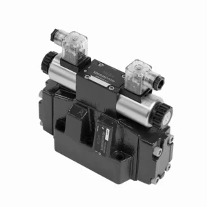
The WEH series directional hydraulic valves of pilot operated are advanced components that provide precise and efficient control over hydraulic systems. Designed to meet the demands of various industries, these valves offer exceptional performance, reliability, and versatility.
The WEH series directional hydraulic valves of pilot operated are reliable, high-performance components that empower operators with precise control and efficient fluid management in hydraulic systems. With their pilot-operated design, exceptional directional control, a wide range of configurations, and high flow capacity, these valves offer the reliability and versatility required in various industries. Following the recommended usage methods and adhering to regular maintenance practices, the WEH series valves will continue delivering exceptional performance. Upgrade your hydraulic system with the WEH series directional hydraulic valves operated and experience the benefits of precision, control, and reliability.
WEH Series Directional Hydraulic Valves Of Pilot Operated Key Characteristics:
- Pilot Operated Design:
- The WEH series valves utilize a pilot-operated design, which enhances their responsiveness and control accuracy.
- This design enables the valves to handle high-pressure applications, ensuring optimal performance easily.
- 方向控制:
- These hydraulic valves excel in providing precise directional control of hydraulic fluid.
- 操作人员可以轻松控制流体流量,并将其导向液压系统内的不同执行器或组件。
- Wide Range of Configurations:
- The WEH series valves are available in various configurations, including various sizes, flow rates, and pressure ratings.
- This versatility allows them to be tailored to specific application requirements and system specifications.
- 高流量:
- These valves are designed to handle high flow rates, making them suitable for applications that demand substantial fluid flow.
- 其优化的内部通道和坚固的结构确保了最小的压力损失和高效的流体管理。
WEH Series Directional Hydraulic Valves Of Pilot Operated Parameter:
NG10
| 规格 | WEH10 type | |||||||||
| Max. operating pressure:P、A、B | 350 | |||||||||
| T 端口 | With external pilot oil drain bar | 315 | ||||||||
| With internal pilot oil drain bar | DC 210 AC 160 | |||||||||
| Y端口 | With external pilot oil drain bar | DC 210 AC 160 | ||||||||
| Min. control pressure | With external pilot oil supply ( not apply to C、Z、 F、G、H、P、T、V) bar |
3-position valve 10 | ||||||||
| Spring-return 2-position valve 10 | ||||||||||
| Hydraulic-return 2-position valve 7 | ||||||||||
| With internal pilot oil supply ( apply to C、Z、F、 G、H、P、T、V) bar |
6.5 | |||||||||
| Max. control pressure bar | 250 | |||||||||
| 体液 | Mineral oil,Phosphate ester | |||||||||
| Fluid temperature range ℃ | -30 to +80 ( NBR seals | |||||||||
| -20 to +80 ( FKM seals ) | ||||||||||
| Viscosity range mm2/秒 | 2.8 至 500 | |||||||||
| Switching pilot oil volume cm3 | 3-position valve 2.04 | |||||||||
| 2-position valve 4.08 | ||||||||||
| Switching times (= Valve switching time from the neutral position to the switched position)(AC and DC ) | ||||||||||
| Control pressure bar | 70 | 140 | 210 | 250 | ||||||
| AC | 直流 | AC | 直流 | AC | 直流 | AC | 直流 | |||
| 3-position valve ms | 30 | 65 | 25 | 60 | 20 | 55 | 15 | 50 | ||
| 2-position valve ms | 35 | 80 | 30 | 75 | 25 | 70 | 20 | 65 | ||
| Switching times (= Valve switching time from the switched position to the neutral position) | ||||||||||
| 3-position valve ms | 30 | |||||||||
| 2-position valve ms | 35 | 40 | 30 | 35 | 25 | 30 | 20 | 25 | ||
| 安装位置 | HC、HD、HK、HZ、HY Type hydraulic-return valves are installed horizontally, the rest can be installed arbitrarily | |||||||||
| Flow of shortest switching time L/min | about 35 | |||||||||
| 重量 | Single solenoid valve kg | 6.7 | ||||||||
| Double solenoid valve kg | 7.1 | |||||||||
| Switching time regulator kg | 1.0 | |||||||||
| Reducing valve kg | 0.5 | |||||||||
NG16
| 规格 | WEH16… type | |||||||||||||
| Max. operating pressure:P、A、B | 350 | |||||||||||||
| T 端口 | With external pilot oil drain bar | 250 | ||||||||||||
| With internal pilot oil drain bar | DC 210 AC 160 | |||||||||||||
| Y端口 | With external pilot oil drain bar | DC 210 AC 160 | ||||||||||||
| Min. control pressure | With external pilot oil supply ( not apply to C、Z、 F、G、H、P、T、V)bar |
3-position valve 14 | ||||||||||||
| Spring-return 2-position valve 14 | ||||||||||||||
| Hydraulic-return 2-position valve 14 | ||||||||||||||
| With internal pilot oil supply ( apply to C、Z、F、 G、 H、P、T、V) bar |
When applying prepressing or the flow is large correspondingly ,enginery of spool valve is 4.5 as C,Z,F,G,H,P,T and V | |||||||||||||
| Max. control pressure bar | 250 | |||||||||||||
| 体液 | Mineral oil,Phosphate ester | |||||||||||||
| Fluid temperature range ℃ | -30 to +80 ( NBR seals | |||||||||||||
| -20 to +80 ( FKM seals ) | ||||||||||||||
| Viscosity range mm2/秒 | 2.8 至 500 | |||||||||||||
| Switching pilot oil volume | ||||||||||||||
| – Spring-centering 3-position valve cm3 | 5.72 | |||||||||||||
| – 2-position valve cm3 | 11.45 | |||||||||||||
| * * Switching times (= Valve switching time from the neutral position to the switched position)(AC and DC) | ||||||||||||||
| Control pressure bar | 50 | 150 | 250 | |||||||||||
| AC | 直流 | AC | 直流 | AC | 直流 | AC | 直流 | AC | 直流 | AC | 直流 | |||
| – Spring-centering 3-position valve ms | 35 | 65 | 30 | 60 | 30 | 58 | ||||||||
| – 2-position valve ms | 45 | 65 | 35 | 55 | 30 | 50 | ||||||||
| **Switching times (= Valve switching time from the neutral position to the switched position) | ||||||||||||||
| – Spring-centering 3-position valve ms | 30 | |||||||||||||
| – 2-position valve ms | 45 | 45 | 35 | 35 | 30 | 30 | ||||||||
| 安装位置 | C,D,K,Z,Y Type hydraulic-return valves are installed horizontally, the rest can be installed arbitrarily | |||||||||||||
| Flow of shortest switching time L/min | about 35 | |||||||||||||
| Weight kg | about 9.5 | |||||||||||||
NG25
| 规格 | WEH25… type | |||||||||||||||||
| Max. operating pressure:P、A、B | 350 | |||||||||||||||||
| T 端口 | With external pilot oil drain bar | 250 | ||||||||||||||||
| With internal pilot oil drain bar | DC 210 AC 160 | |||||||||||||||||
| Y端口 | With external pilot oil drain bar | DC 210 AC 160 | ||||||||||||||||
| Min. control pressure | With external pilot oil supply ( not apply to C、Z、F、 G、H、P、T、V) bar |
Spring-centering 3-position valve 13 | ||||||||||||||||
| Spring-return 2-position valve 13 | ||||||||||||||||||
| Hydraulic-return 2-position valve 8 | ||||||||||||||||||
| With internal pilot oil supply ( apply to C、Z、F、 G、H、P、T、V) bar |
When applying prepressing or the flow is large correspondingly ,enginery of spool valve is 4.5 as C,Z,F,G,H,P,T and V | |||||||||||||||||
| Max. control pressure bar | 250 | |||||||||||||||||
| 体液 | Mineral oil,Phosphate ester | |||||||||||||||||
| Fluid temperature range ℃ | -30 to +80 ( NBR seals | |||||||||||||||||
| -20 to +80 ( FKM seals ) | ||||||||||||||||||
| Switching pilot oil volume | ||||||||||||||||||
| – Spring-centering 3-position valve cm3 | 14.2 | |||||||||||||||||
| – 2-position valve cm3 | 28.4 | |||||||||||||||||
| * Switching times (= Valve switching time from the neutral position to the switched position)(AC and DC) | ||||||||||||||||||
| Control pressure bar | 50 | 140 | 210 | 250 | ||||||||||||||
| AC | 直流 | AC | 直流 | AC | 直流 | AC | 直流 | |||||||||||
| – Spring-centering 3-position valve ms | 50 | 85 | 40 | 75 | 35 | 70 | 30 | 65 | ||||||||||
| – 2-position valve ms | 120 | 160 | 100 | 130 | 85 | 120 | 70 | 105 | ||||||||||
| *Switching times (= Valve switching time from the neutral position to the switched position) | ||||||||||||||||||
| – Spring-centering 3-position valve ms | 40 | |||||||||||||||||
| – 2-position valve ms | 120 | 125 | 95 | 100 | 85 | 90 | 75 | 80 | ||||||||||
| 安装位置 | C,D,K,Z,Y Type hydraulic-return valves are installed horizontally, the rest can be installed arbitrarily | |||||||||||||||||
| Flow of shortest switching time L/min | about 35 | |||||||||||||||||
| Weight kg | about 18 | |||||||||||||||||
NG32
| 规格 | WEH32… type | |||||||||||||
| Max. operating pressure:P、A、B | 350 | |||||||||||||
| T 端口 | With external pilot oil drain bar | 250 | ||||||||||||
| With internal pilot oil drain bar | DC 210 AC 160 | |||||||||||||
| Y端口 | With external pilot oil drain bar | DC 210 AC 160 | ||||||||||||
| Min. control pressure | With external pilot oil supply
With internal pilot oil supply |
3-position valve 8.5 | ||||||||||||
| Spring-return 2-position valve 10 | ||||||||||||||
| Hydraulic-return 2-position valve 15 | ||||||||||||||
| With internal pilot oil supply ( apply to C、Z、F、 G、H、P、T、V) bar |
When applying prepressing or the flow is large correspondingly ,enginery of spool valve is 4.5 as C,Z,F,G,H,P,T and V | |||||||||||||
| Max. control pressure bar | 250 | |||||||||||||
| 体液 | Mineral oil,Phosphate ester | |||||||||||||
| Fluid temperature range ℃ | -30 to +80 ( NBR seals | |||||||||||||
| -20 to +80 ( FKM seals ) | ||||||||||||||
| Viscosity range mm2/秒 | 2.8 至 500 | |||||||||||||
| Switching pilot oil volume | ||||||||||||||
| – Spring-centering 3-position valve cm3 | 29.4 | |||||||||||||
| – 2-position valve cm3 | 58.8 | |||||||||||||
| * Switching times (= Valve switching time from the neutral position to the switched position)(AC and DC) | ||||||||||||||
| Control pressure bar | 50 | 150 | 250 | |||||||||||
| AC | 直流 | AC | 直流 | AC | 直流 | |||||||||
| – Spring-centering 3-position valve ms | 65 | 80 | 50 | 90 | 35 | 105 | ||||||||
| – 2-position valve ms | 100 | 130 | 75 | 100 | 60 | 115 | ||||||||
| *Switching times (= Valve switching time from the neutral position to the switched position) | ||||||||||||||
| – Spring-centering 3-position valve ms | ( DC :50,AC :60) | |||||||||||||
| – 2-position valve ms | 115 | 90 | 35 | 70 | 65 | 65 | ||||||||
| 安装位置 | C、D、K、Z、YType hydraulic-return valves are installed horizontally, the rest can be installed arbitrarily | |||||||||||||
| Flow of shortest switching time L/min | about 50 | |||||||||||||
| Weight kg | about 36 | |||||||||||||
WEH Series Directional Hydraulic Valves Of Pilot Operated Advantages:
• Electrohydraulic directioanl valve directioanls the oil path by controlling the main spool
• WEH electrohydraulic control
• Installation face follow DIN 24340 A, ISO 4401 and CETOP-RP 121H Sub-plate mounting connection
• Wet DC or AC solenoid (optional)
• With manual emergency control
• Electropneumatic connection as single or center connection
• Spring or hydraulic alignment or bias
Usage Method Of WEH Series Directional Hydraulic Valves Of Pilot Operated:
- 系统集成:
- Identify the optimal location for installing the WEH series valves within the hydraulic system, considering the desired flow path and control requirements.
- 确保与系统的压力和流量规格兼容。
- 使用合适的支架或安装配件将阀门牢固地安装好。
- Pilot Control Setup:
- Connect the pilot control lines to the designated ports on the valves, following the manufacturer’s instructions.
- Ensure proper sizing and routing of the pilot lines to maintain optimal control signal integrity.
- 流体连接:
- 选择兼容的液压接头和软管,以实现安全无泄漏的连接。
- 安装过程中,请遵循制造商的说明,使用正确的扭矩值。
- 使用合适的螺纹密封剂或胶带,以确保密封可靠。
- 控制与调节:
- To operate the WEH series valves, utilize the recommended control method, such as manual levers or electrical controls.
- Adjust the valves’ settings to achieve the desired flow direction and rates, ensuring optimal performance.
How Do Hydraulic Valve Lifters Work?
Hydraulic valve lifters, also known as hydraulic tappets or hydraulic lash adjusters, play a vital role in the proper operation of an internal combustion engine. They are responsible for maintaining the proper clearance, or “lash,” between the engine’s camshaft and valve train components. Here’s an overview of how hydraulic valve lifters work:
- 结构:
- Hydraulic valve lifters are small cylindrical devices typically made of metal.
- They are between the camshaft and the engine’s valve train components, such as the pushrods, rocker arms, or overhead cam followers.
- Hydraulic Operation:
- Inside the hydraulic valve lifter, a small piston mechanism operates based on hydraulic pressure.
- The lifter is filled with hydraulic fluid, typically engine oil, which acts as a working fluid.
- Camshaft Interaction:
- The camshaft has lobes or eccentric shapes that push against the lifters as it rotates.
- As the camshaft lobe comes into contact with the lifter, it applies a force that compresses its internal piston.
- Lash Adjustment:
- When the lifter’s piston is compressed, it pushes the hydraulic fluid out of the lifter through a small orifice.
- This hydraulic fluid is expelled into the engine’s oil galleries or passages.
- Lash Compensation:
- The expelled hydraulic fluid creates a hydraulic cushion or “spring” effect, compensating for any clearance or lash between the camshaft lobe and the valve train components.
- This compensation eliminates excessive clearance and ensures that the valve train remains in constant contact with the camshaft lobes.
- Maintenance of Lash:
- If there is excessive clearance or lash in the valve train due to wear or other factors, the lifter’s internal piston will extend further to maintain the necessary hydraulic pressure.
- This extended position allows the lifter to take up the additional clearance, thus maintaining proper valve lash.
- Oil Pressure and Lubrication:
- The hydraulic valve lifters rely on the engine’s oil pressure for proper operation.
- The oil pump circulates oil through the engine, and the lifters receive a continuous oil supply to maintain hydraulic pressure and lubrication.
工厂的能力和产能:
(1) 装配
我们拥有一流的自主研发装配平台。液压油缸生产车间拥有 4 条半自动提升油缸装配线和 1 条全自动倾斜油缸装配线,设计年生产能力 100 万支。特种油缸车间配备了各种规格的半自动清洗装配系统,设计年生产能力 20 万只,并配备了知名数控加工设备、加工中心、高精度油缸加工专用设备、机器人焊接机、自动清洗机、油缸自动装配机、自动喷漆生产线等。现有关键设备 300 多台(套)。设备资源的优化配置和高效利用,保证了产品的精度要求,满足了产品的高质量需求。


(2) 机加工
加工车间配备了定制的斜轨车削中心、加工中心、高速珩磨机、焊接机器人及其他相关设备,可加工最大内径 400 毫米、最大长度 6 米的气缸管。

(3) 焊接

(4) 油漆和涂料
配备中小型圆筒自动水性漆喷涂线,实现机器人自动上下料和自动喷涂,设计产能为每班 4000 件;
我们还拥有一条由动力链驱动的大型油缸半自动喷漆生产线,设计产能为每班 60 箱。


(5) 测试
我们拥有一流的检验设施和试验台,确保气缸的性能符合要求。

我们是最好的液压缸制造商之一。我们能够提供全面的液压缸。我们还提供相应的 农用齿轮箱凭借卓越的产品质量和售后服务,我们的产品远销世界各地,赢得了良好的声誉。我们欢迎国内外客户与我们联系洽谈业务、交流信息,并 与我们合作!
液压缸应用:
