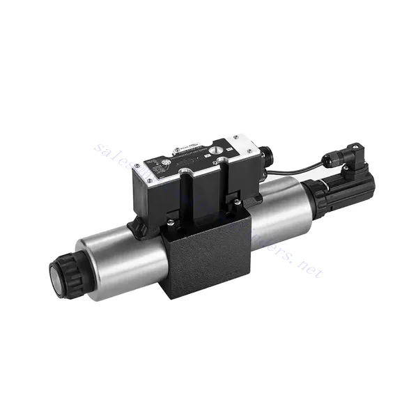
4WRE(E) Series Proportional Directional Hydraulic Valve
4WRE(E) Series Proportional Directional Hydraulic Valve
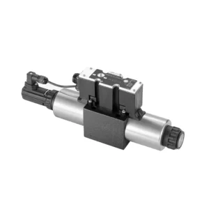
The 4WRE(E) series proportional directional hydraulic valve is a cutting-edge hydraulic component designed to deliver precise control and exceptional performance in hydraulic systems. This valve utilizes advanced proportional control technology to ensure accurate flow regulation and seamless directional changes.
The 4WRE(E) series proportional directional hydraulic valve empowers hydraulic systems with precise flow control, versatile directional changes, and energy efficiency. Its proportional control technology enables accurate and responsive flow adjustment, while the high flow capacity ensures reliable performance even in demanding applications. By following the recommended usage methods and maintenance guidelines, you can maximize the benefits and longevity of the 4WRE(E) series valve, elevating your hydraulic system to new levels of precision and performance. Upgrade your hydraulic setup today and experience the power of the 4WRE(E) series proportional directional hydraulic valve.
4WRE(E) Series Proportional Directional Hydraulic Valve Key Characteristics:
- Proportional Control Technology:
- The 4WRE(E) series valve features advanced proportional control technology, allowing for precise and proportional flow adjustment according to control signals.
- This feature enables accurate and responsive control, resulting in improved system performance and efficiency.
- 多功能方向控制:
- With its proportional directional control capability, this valve offers versatile control over hydraulic fluid direction.
- It allows for seamless activation and deactivation of hydraulic components such as cylinders, motors, and actuators in different directions, enhancing system flexibility and productivity.
- 高流量:
- The 4WRE(E) series valve is designed to handle high flow rates, making it suitable for applications requiring substantial hydraulic power.
- 其坚固的结构确保即使在苛刻的条件下也能可靠运行,提供稳定高效的流量控制。
- 能源效率:
- By employing advanced flow control mechanisms, this valve minimizes pressure drops and optimizes energy usage.
- 它有助于降低能源消耗,从而节省成本并带来环境效益。
4WRE(E) Series Proportional Directional Hydraulic Valve Parameter:
| 液压 | ||||
| 安装位置 | 可选,最好是水平的 | |||
| 尺寸 | 6 | 10 | ||
| 重量 | 4WRE…L2X | 公斤 | 2.2 | 6.3 |
| 4WREE…L2X | 2.4 | 6.5 | ||
| Nominal flow qnom at Δp = 10 bar | 升/分钟 | 8 16 32 | 25 50 75 | |
| 滞后 | % | ≤0.1 | ||
| Reversal span | % | ≤0.05 | ||
| 重复性 | % | ≤0.05 | ||
| 最大工作压力 | 端口动态血压 | 酒吧 | 315 | |
| T 端口 | 酒吧 | 210 | ||
| 体液 | 适用于 NBR 和 FKM 密封件的矿物油 | |||
| FKM密封用磷酸酯 | ||||
| Ambient air temperature range | 4WRA…L2X | ℃ | -20℃ to 70℃ (-4°F to 158°F) | |
| 4WRAE…L2X | ℃ | -20℃ to 50℃ (-4°F to 122°F) | ||
| 粘度范围 | 毫米²/秒 | 20 至 380(最好是 30 至 46) | ||
| 污染程度 | NAS1638 class9 或 ISO 4406 class 20/18/15 | |||
| 电气数据 | ||||
| 1)螺线管 | ||||
| 尺寸 | 6 | 10 | ||
| 电压类型 | 直流 | |||
| 控制值信号 | ±10V或4~20mA | |||
| Max.current per solenoid | 一个 | 2.5 | ||
| 线圈电阻 | 冷值 | Ω | 2.7 | 3.7 |
| 最大保温值 | 4.05 | 5.55 | ||
| 责任 | % | ED 100% | ||
| 线圈温度 | ℃ | 150 | ||
| 阀门保护符合 EN 60529 标准 | IP 65 | |||
| 2) Control electronics | ||||
| 放大器 | 4WRE…L2X | VT-VSPA2-L2X | ||
| 4WREE…L2X | integrated(OBE) | |||
| 工作电压 | 标称电压 | 虚拟数据中心 | 24 | |
| 下限值 | 五 | 19.4 | ||
| 上限值 | 五 | 35 | ||
| 放大器电流消耗 | 巨幕 | 一个 | < 2 | |
| 巨幕 | 一个 | 3 | ||
4WRE(E) Series Proportional Directional Hydraulic Valve Advantages:
• 直动式比例方向阀,用于控制液体流动的流量和方向
• 面板式安装
• 比例电磁铁通过螺纹连接驱动阀芯,线圈可单独拆卸
• Spool position feedback
• 可选内置放大器,4WRAE…L2X 型输入可以是 A1 或 F1
• 配套外部放大器电源
Usage Method Of 4WRE(E) Series Proportional Directional Hydraulic Valve:
- 系统评估:
- 评估您的液压系统,并确定具体的流量和方向控制要求。
- Determine if the 4WRE(E) series valve is suitable based on its flow capacity, pressure rating, and compatibility with your system.
- 阀门选择:
- Select the appropriate variant of the 4WRE(E) series valve based on your system parameters, flow requirements, and directional control needs.
- 考虑最大流量、压力等级、响应时间和操作条件等因素。
- 安装:
- 请仔细按照制造商的安装说明进行操作,确保阀门正确对准并牢固安装。
- Make leak-free connections and ensure correct flow direction alignment to guarantee optimal performance.
- 控制信号连接:
- 将阀门的控制信号线连接到合适的控制装置,例如比例放大器或电子控制单元。
- 确保阀门与控制装置之间接线正确且兼容,以实现精确、灵敏的控制。
How To Adjust Valves With Hydraulic Lifters?
调整液压挺杆的气门间隙是一项至关重要的维护工作,可以确保发动机性能正常,并防止气门噪音大或功率下降等问题。以下是调整液压挺杆气门间隙的分步指南:
- 准备:
- 在开始调整过程之前,确保发动机已关闭并冷却。
- 熟悉发动机的点火顺序以及制造商为您的发动机型号提供的具体气门间隙规格。
- 识别正确的气缸:
- 参照发动机的点火顺序图,找到发动机的点火位置。
- 确定与您要调整的特定阀门相对应的气缸。
- 定位圆柱体:
- 使用套筒扳手或发动机内置的转动机构手动旋转发动机曲轴。
- 将要调整的气缸定位在压缩冲程的上止点 (TDC)。您可以通过对齐曲轴皮带轮上的正时标记或使用活塞止动工具来做到这一点。
- 松开摇臂:
- 找到您想要调整的特定阀门上的摇臂。
- 使用合适的扳手或套筒松开摇臂螺母或调节螺钉。
- 调整气门间隙:
- 摇臂松开后,就可以调整气门间隙了。气门间隙是指摇臂和气门杆之间的间隙。
- 使用塞尺测量现有的气门间隙。将合适的厚度计插入摇臂和气门杆之间。
- 如果间隙过紧,即塞尺无法插入或阻力过大,则需要增大气门间隙。如果间隙过松,即塞尺插入过于容易,则需要减小气门间隙。
- 要调整气门间隙,请相应地拧紧或松开摇臂螺母或调节螺钉。请参阅制造商的规格,了解建议的调整量。
- 重新检查气门间隙:
- 调整后,使用塞尺重新检查气门间隙,以确保其符合建议的规格。
- 如有必要,重复调整过程,直到达到正确的气门间隙。
- 对其他气缸重复此操作:
- 按照点火顺序继续下一个气缸,并对要调整的每个气缸重复步骤 4 至 6。
- 在调整气门间隙之前,请记住旋转曲轴并将每个气缸定位在压缩冲程的上止点。
- 固定摇臂:
- 一旦每个气缸的气门间隙都调整到适当位置,就将摇臂螺母或调节螺钉拧紧至制造商建议的扭矩规格。
- 拧紧后,再次检查气门间隙是否保持在规定范围内。
- 最终检查:
- 旋转发动机曲轴几次,确保旋转平稳,并检查是否有任何异常噪音或阻力。
- 启动发动机,聆听气门是否有任何异常噪音。如果听到过度敲击声或敲击声,请重新检查气门间隙调节。
工厂的能力和产能:
(1) 装配
我们拥有一流的自主研发装配平台。液压油缸生产车间拥有 4 条半自动提升油缸装配线和 1 条全自动倾斜油缸装配线,设计年生产能力 100 万支。特种油缸车间配备了各种规格的半自动清洗装配系统,设计年生产能力 20 万只,并配备了知名数控加工设备、加工中心、高精度油缸加工专用设备、机器人焊接机、自动清洗机、油缸自动装配机、自动喷漆生产线等。现有关键设备 300 多台(套)。设备资源的优化配置和高效利用,保证了产品的精度要求,满足了产品的高质量需求。


(2) 机加工
加工车间配备了定制的斜轨车削中心、加工中心、高速珩磨机、焊接机器人及其他相关设备,可加工最大内径 400 毫米、最大长度 6 米的气缸管。

(3) 焊接

(4) 油漆和涂料
配备中小型圆筒自动水性漆喷涂线,实现机器人自动上下料和自动喷涂,设计产能为每班 4000 件;
我们还拥有一条由动力链驱动的大型油缸半自动喷漆生产线,设计产能为每班 60 箱。


(5) 测试
我们拥有一流的检验设施和试验台,确保气缸的性能符合要求。

我们是最好的液压缸制造商之一。我们能够提供全面的液压缸。我们还提供相应的 农用齿轮箱凭借卓越的产品质量和售后服务,我们的产品远销世界各地,赢得了良好的声誉。我们欢迎国内外客户与我们联系洽谈业务、交流信息,并 与我们合作!