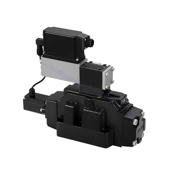
4WRLE系列先导式比例方向液压阀
4WRLE系列先导式比例方向液压阀
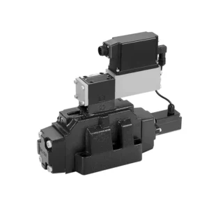
The 4WRLE series pilot-operated proportional directional hydraulic valve is a cutting-edge hydraulic component that revolutionizes fluid control in hydraulic systems. This valve combines pilot-operated technology with proportional directional control, offering precise flow regulation and exceptional efficiency.
The 4WRLE series pilot-operated proportional directional hydraulic valve elevates hydraulic control to new heights of precision and efficiency. With its pilot-operated technology and proportional directional control, this valve ensures accurate flow regulation, optimized energy consumption, and enhanced system performance. By following the recommended usage methods and maintenance guidelines, you can unleash the full potential of the 4WRLE series valve and achieve superior hydraulic control. Upgrade your hydraulic system today and experience the power of precision with the 4WRLE series pilot-operated proportional directional hydraulic valve.
4WRLE Series Pilot Operated Proportional Directional Hydraulic Valve Key Characteristics:
- Pilot Operated Technology:
- The 4WRLE series valve incorporates pilot-operated technology, allowing precise fluid flow control and pressure regulation.
- This technology enables efficient energy usage and reduces heat generation, resulting in improved overall system performance and reduced operating costs.
- Proportional Directional Control:
- With its proportional directional control capability, this valve provides accurate and balanced flow adjustment based on control signals.
- The proportional control allows for smooth and precise control of hydraulic actuators, enhancing system performance and minimizing wear and tear.
- 多功能:
- The 4WRLE series valve offers versatile control over fluid direction, making it suitable for a wide range of hydraulic applications.
- Whether it’s controlling cylinders, motors, or other hydraulic components, this valve ensures seamless activation and deactivation in different directions, enhancing system flexibility and adaptability.
- 高流量:
- Designed to handle high flow rates, the 4WRLE series valve delivers exceptional performance even in demanding applications.
- Its robust construction and optimized flow channels ensure reliable operation and consistent flow control, meeting the requirements of high-power hydraulic systems.
4WRLE Series Pilot Operated Proportional Directional Hydraulic Valve Parameter:
NG6
| 一般的 | |||||||
| 设计 | Spool valve, direct operated, with steel sleeve | ||||||
| 驱动 | Proportional solenoid with position control, OBE | ||||||
| 连接类型 | Subplate mounting, porting pattern according to ISO 4401-03-02-0-05 | ||||||
| 安装位置 | Any | ||||||
| 环境温度范围 | ℃ | -20…+50 | |||||
| 重量 | 公斤 | about 2.75 | |||||
| Maximum vibration resistance (test condition) | Max. 25 g, space vibration test in all directions (24h) | ||||||
| 液压 (measured at p=100bar, with HLP46 at ϑoil = 40℃ ±5℃) | |||||||
| 压力流体 | Mineral oil (HL, HLP)to DIN 51 524 | ||||||
| 粘度范围 | 受到推崇的 | 毫米²/秒 | 20…100 | ||||
| 最大允许值 | 毫米²/秒 | 10…800 | |||||
| 压力流体温度范围 | ℃ | -20 至 +70 | |||||
| 压力流体的最大允许污染程度 纯度等级符合 ISO 4406 (c) | 18/16/13班 | ||||||
| Rated flow (Δp = 35 bar per edge) | 升/分钟 | 2 | 4 | 12 | 24 | 40 | |
| 最大工作压力 | 酒吧 | Port A、B、P:315 | |||||
| Max. pressure | 酒吧 | Port T: 250 | |||||
| Leakage flow at 100 bar | Linear | cm³/min | <150 | <180 | <300 | <500 | <900; |
| Nonlinear | cm³/min | / | / | / | <300 | <450; | |
| 静态/动态 | |||||||
| 滞后 | % | ≤0.2 | |||||
| Actuating time for signal step 0 … 100% | 多发性硬化症 | 10 | |||||
| Temperature drift | Zero shift < 1% at ΔT=40℃ | ||||||
| Zero compensation | Ex factory ±1% | ||||||
| Electric, control electronics integrated in the valve | |||||||
| Relative duty cycle | % | 100ED | |||||
| 保护程度 | IP65 | ||||||
| 联系 | Plug-in connector 6P+PE, DIN 43563 | ||||||
| Supply voltage Terminal A Terminal B |
24VDCnom | ||||||
| min. 21VDC / max. 40VDC | |||||||
| 0V (ripple max. 2) | |||||||
| Fuse protection, external | AF | 2.5 | |||||
| nput, version “A1” Terminal D (UE) Terminal E |
Differential amplifier, Ri = 100 kΩ | ||||||
| 0…±10V | |||||||
| 0V | |||||||
| Input, version “F1” Terminal D (ID-E) Terminal E (ID-E) |
Load, Rsh = 200 Ω | ||||||
| 4…12…20mA | |||||||
| Current loop ID-E return | |||||||
| Test signal, version “A1” Terminal F (UTest) Terminal C |
LVDT | ||||||
| 0…±10V | |||||||
| Reference 0 V | |||||||
| Test signal, version “F1” Terminal F ( I F-C ) Terminal C ( I F-C ) |
LVDT signal 4 … (12) … 20 mA on external load 200 … 500 Ωmaximum | ||||||
| 4 … (12) … 20mA (output) | |||||||
| Current loop IF-C return | |||||||
| Adjustment | Calibrated before delivery, see characteristic curves | ||||||
NG10
| 一般的 | |||||
| 设计 | Spool valve, directly operated, with steel sleeve | ||||
| 驱动 | Proportional solenoid with position control, OBE | ||||
| 连接类型 | Plate port, porting pattern (ISO 4401-05-04-0-05) | ||||
| 安装位置 | Any | ||||
| 环境温度范围 | ℃ | -20…+50 | |||
| 重量 | 公斤 | about 7.1 | |||
| Maximum vibration resistance (test condition) | Max. 25 g, space vibration test in all directions (24h) | ||||
| Hydraulic (measured with HLP 46, ϑoil =40℃ ±5℃) | |||||
| 压力流体 | Hydraulic oil according to DIN 51524…535 | ||||
| 粘度范围 | 受到推崇的 | 毫米²/秒 | 20…100 | ||
| Max. permitted | 毫米²/秒 | 10…800 | |||
| 压力流体温度范围 | ℃ | -20 至 +70 | |||
| Max. admissible degree of contamination of the hydraulic fluid,cleanliness class according to ISO 4406 (c) | 18/16/13班 | ||||
| Rated flow(Δp = 35 bar per edge) | 升/分钟 | 50 | 100 | ||
| 最大工作压力 | 酒吧 | Port P A B: 315 | |||
| Max. pressure | 酒吧 | Port T: 250 | |||
| Leakage flow at 100 bar | Linear | cm³/min | <1200 | <1500 | |
| Nonlinear | cm³/min | <600 | <600 | ||
| 静态/动态 | |||||
| 滞后 | % | ≤0.2 | |||
| Actuating time for signal step 0 … 100% | 多发性硬化症 | 25 | |||
| Temperature drift | Zero shift < 1% at ΔT=40℃ | ||||
| Zero compensation | Ex factory ±1% | ||||
| Electric, control electronics integrated in the valve | |||||
| Relative duty cycle | % | 100ED | |||
| 保护程度 | IP65(with mating connector mounted and locked ) | ||||
| 联系 | Mating connector 6P+PE, DIN 43563 | ||||
| Supply voltage Terminal A Terminal B |
24VDCnom | ||||
| min. 21VDC / max. 40VDC | |||||
| Ripple max. 2 VDC | |||||
| Fuse protection, external | AF | 2.5 | |||
| Input, version “A1” Terminal D (UE) Terminal E |
Differential amplifier, Ri = 100 kΩ | ||||
| 0…±10V | |||||
| 0V | |||||
| Input, version “F1” Terminal D (ID-E) Terminal E (ID-E) |
Load, Rsh = 200 | ||||
| 4…12…20mA | |||||
| Current loop ID-E return | |||||
| Test signal, version “A1” Terminal F (U测试) Terminal C |
LVDT | ||||
| 0…±10V | |||||
| Reference 0 V | |||||
| Test signal, version “F1” Terminal F ( I F-C ) Terminal C ( I F-C ) |
LVDT | ||||
| 4…20 mA output | |||||
| Current loop IF-C feedback | |||||
4WRLE Series Pilot Operated Proportional Directional Hydraulic Valve Advantages:
• Direct-acting servo solenoid valve with control piston and valve sleeve, with servo performance
• Single-side drive, optional, with power-off safety function
Control solenoid with built-in feedback and integrated amplifier board (OBE), factory preset
• Electrical connection 6P+PE signal input differential amplifier with interface, input optional A1: ±10V, or interface F1: 4…20mA (Rsh =200Ω)
• Panel mounting: the mounting surface complies with ISO 4401-03-02
Usage Method Of 4WRLE Series Pilot Operated Proportional Directional Hydraulic Valve:
- System Assessment:
- Evaluate your hydraulic system and define the specific flow and directional control requirements.
- Identify whether the 4WRLE series valve is compatible with your system based on factors such as flow capacity, pressure rating, and compatibility with your application.
- 阀门选择:
- Select the appropriate variant of the 4WRLE series valve based on your system parameters, flow requirements, and directional control needs.
- Consider factors such as maximum flow rate, pressure rating, response time, and environmental operating conditions.
- 安装:
- Follow the manufacturer’s installation instructions carefully to ensure proper alignment and secure valve mounting.
- Create leak-free connections and ensure correct flow direction alignment to guarantee optimal performance.
- Control Signal Integration:
- 将阀门的控制信号线连接到合适的控制装置,例如比例放大器或电子控制单元。
- Ensure proper wiring and compatibility between the valve and control device to achieve accurate and responsive control.
如何连接液压流量控制阀?
要连接液压流量控制阀,请按照以下步骤操作:
- 识别阀门类型: 确定您所使用的流量控制阀的具体类型。常见类型包括针阀、可调流量控制阀或压力补偿流量控制阀。确保该阀门适合您的应用,并与您的液压系统兼容。
- 准备所需工具和材料: 收集必要的工具和材料,包括合适的液压接头、适配器、软管和扳手。
- 准备液压系统: 关闭液压系统,并通过启动溢流阀或缩回液压缸来释放系统内的所有压力。这一步骤对于安全至关重要。
- 确定流动方向: 确定液压系统中的流体流动方向。通常,流体流动方向由液压元件上的箭头指示。在继续操作之前,请务必确认流体流动方向正确。
- 确定安装点: 确定液压系统中流量控制阀的最佳安装位置。考虑的因素包括:易于接近性、与执行器或液压元件的距离以及调节的便捷性。
- 安装阀门: 使用合适的支架或夹具将流量控制阀牢固地安装在选定位置。确保阀门位置正确,使进出口与流体流动方向一致。
- 连接进水口和出水口: 将液压软管或管路连接到流量控制阀的进出口。使用合适的液压接头和适配器,确保连接处无泄漏。用扳手拧紧连接处,确保牢固连接,但避免过度拧紧。
- 调整流量控制: 根据流量控制阀的类型,它可能具有可调节功能,例如针阀或流量控制旋钮。根据所需的流量或速度调节阀门。有关具体的调节步骤,请参阅制造商的说明。
- 测试系统: 安装并调整好流量控制阀后,缓慢恢复液压系统压力。测试系统以确保流量控制阀正常工作。监测液压执行器的流量或速度,确认其在所需范围内。
- 微调和监控: 调节流量控制阀以达到所需的流量或速度。定期检查液压系统,查看是否存在泄漏、压力不稳定或异常情况。
工厂的能力和产能:
(1) 装配
我们拥有一流的自主研发装配平台。液压油缸生产车间拥有 4 条半自动提升油缸装配线和 1 条全自动倾斜油缸装配线,设计年生产能力 100 万支。特种油缸车间配备了各种规格的半自动清洗装配系统,设计年生产能力 20 万只,并配备了知名数控加工设备、加工中心、高精度油缸加工专用设备、机器人焊接机、自动清洗机、油缸自动装配机、自动喷漆生产线等。现有关键设备 300 多台(套)。设备资源的优化配置和高效利用,保证了产品的精度要求,满足了产品的高质量需求。


(2) 机加工
加工车间配备了定制的斜轨车削中心、加工中心、高速珩磨机、焊接机器人及其他相关设备,可加工最大内径 400 毫米、最大长度 6 米的气缸管。

(3) 焊接

(4) 油漆和涂料
配备中小型圆筒自动水性漆喷涂线,实现机器人自动上下料和自动喷涂,设计产能为每班 4000 件;
我们还拥有一条由动力链驱动的大型油缸半自动喷漆生产线,设计产能为每班 60 箱。


(5) 测试
我们拥有一流的检验设施和试验台,确保气缸的性能符合要求。

我们是最好的液压缸制造商之一。我们能够提供全面的液压缸。我们还提供相应的 农用齿轮箱凭借卓越的产品质量和售后服务,我们的产品远销世界各地,赢得了良好的声誉。我们欢迎国内外客户与我们联系洽谈业务、交流信息,并 与我们合作!


