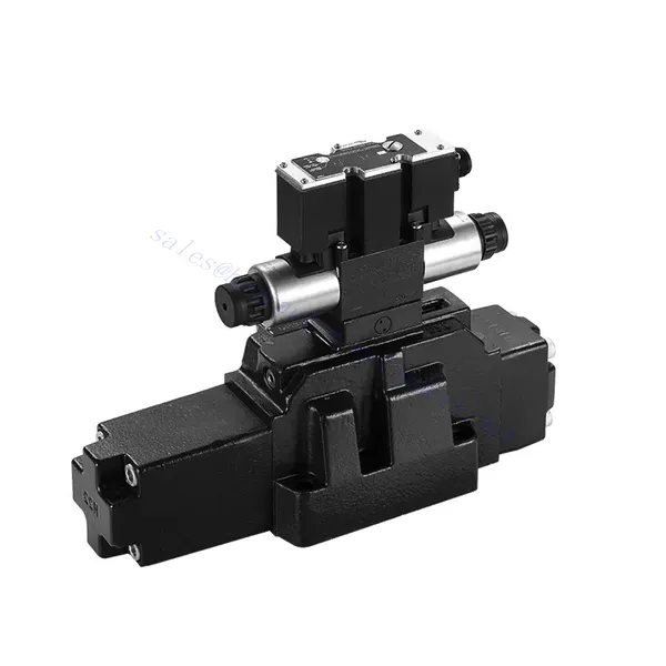
4WRZ/H(E)-serien pilotstyret proportional retningsbestemt hydraulisk ventil
4WRZ/H(E)-serien pilotstyret proportional retningsbestemt hydraulisk ventil
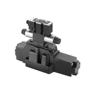
The 4WRZ/H(E) series pilot-operated proportional directional hydraulic valve is a state-of-the-art component designed to provide exceptional precision, control, and efficiency in hydraulic systems. With its advanced pilot-operated proportional control technology, this valve enables accurate flow regulation and seamless directional changes.
The 4WRZ/H(E) series pilot-operated proportional directional hydraulic valve empowers hydraulic systems with precise flow control, versatile directional changes, and energy efficiency. Its pilot-operated proportional control technology ensures accurate and responsive flow adjustment, while the high flow capacity guarantees reliable performance even in demanding applications. By following the recommended usage methods and maintenance guidelines, you can maximize the benefits and longevity of the 4WRZ/H(E) series valve, elevating your hydraulic system to new levels of precision and control. Upgrade your hydraulic setup today and experience the power of the 4WRZ/H(E) series pilot-operated proportional directional hydraulic valve.
4WRZ/H(E) Series Pilot Operated Proportional Directional Hydraulic Valve Key Characteristics:
- Pilotstyret proportionalstyring
- The 4WRZ/H(E) series valve utilizes pilot-operated proportional control technology, allowing precise and proportional flow adjustment based on control signals.
- Denne funktion sikrer præcis og responsiv styring, hvilket resulterer i forbedret systemydelse, reduceret energiforbrug og øget produktivitet.
- Alsidig retningskontrol
- Denne ventil tilbyder alsidig kontrol over hydraulikvæskens retning, hvilket gør den velegnet til en bred vifte af anvendelser.
- Det muliggør problemfri aktivering og deaktivering af hydrauliske komponenter såsom cylindre, motorer og aktuatorer i forskellige retninger, hvilket forbedrer systemets fleksibilitet og tilpasningsevne.
- Høj flowkapacitet
- The 4WRZ/H(E) series valve is engineered to handle high flow rates, making it ideal for applications that require substantial hydraulic power.
- Dens robuste konstruktion sikrer pålidelig ydeevne selv under krævende forhold og giver ensartet og effektiv flowkontrol.
- Energieffektivitet
- Ved at indbygge pilotstyret proportionalstyring minimerer denne ventil trykfald og optimerer energiforbruget.
- Det hjælper med at reducere energiforbruget, hvilket resulterer i omkostningsbesparelser og miljømæssige fordele.
4WRZ/H(E) Series Pilot Operated Proportional Directional Hydraulic Valve Parameter:
| GeneraL | |||||||
| Valve type | WRZ | WRZE | |||||
| Installation | Optional,preferably horizontal | ||||||
| Opbevaringstemperaturområde | ℃ | -20 til +80 | |||||
| Omgivelsestemperaturområde | ℃ | -20 til +70 | -20 til +50 | ||||
| Vægt | NS 10 | kg | 7.8 | 8 | |||
| NS 16 | kg | 13.4 | 13.6 | ||||
| NS 25 | kg | 18.2 | 18.4 | ||||
| NS 32 | kg | 42.2 | 42.4 | ||||
| Hydraulisk (measured with HLPAG.p=100bar : 40 ℃ ± 5 ℃) | |||||||
| Størrelse | 10 | 16 | 25 | 32 | |||
| Driftstryk | Pilot valve | External pilot oil supply | bar | 30 to 100 bar | |||
| Internal pilot oil supply | bar | 100 to 350 with “D3” only | |||||
| Hovedventil | bar | to 315 | til 350 | til 350 | til 350 | ||
| Returtryk | Port T (Port R) (external pilot oil drain)) | bar | to 315 | to 250 | to 250 | til 150 | |
| Port T (internal pilot oil drain) | bar | to 30 | to 30 | to 30 | to 30 | ||
| Port Y | bar | to 30 | to 30 | to 30 | to 30 | ||
| Pilot oil volume input signal 0- 100 % | cm3 | 1.7 | 4.6 | 10 | 26.5 | ||
| Pilot oil flow in port X and Y with a stepped input signal 0- 100 % | 3.5 | 5.5 | 7 | 15.9 | |||
| Flow of the main valve | l/min | to 170 | to 460 | to 870 | to 1600 | ||
| Hydraulic fluid | l/min | Mineral oil (HL, HLP) to DIN 51524 Further fluids on enquiry | |||||
| Hydraulic fluid temperature range | ℃ | -20 to +80(preferably +40 to +50) | |||||
| Viskositetsområde | mm2/s | 20 to 380(preferably 30 to 46) | |||||
| Grad af forurening | Maximum permissible degree of contamination of the pressure fluid is to NAS 1638 or ISO 4406(c) | A filter with a minimum retention rate of βx ≥ 75 is recommended | |||||
| Pilot valve | NAS 1638 class 7 | x=5 | |||||
| Hovedventil | NAS 1638 class 9 | x=15 | |||||
| Hysterese | % | ≤6 | |||||
| Elektrisk | |||||||
| Valve type | WRZ | WRZE | |||||
| Type of protection of the valve to EN 60529 | IP65 with cable socket mounted and locked | ||||||
| Spændingstype | DC | ||||||
| Command value overlap | % | 15 | |||||
| Max. current | EN | 1.5 | 2.5 | ||||
| Solenoid coil resisance | Cold value at 20℃ | Ω | 4.8 | 2 | |||
| Maks. varm værdi | Ω | 7.2 | 3 | ||||
| Cyklisk varighedsfaktor | % | 100 | |||||
| Spoletemperatur | ℃ | til 150 | |||||
| Ventilbeskyttelse i henhold til EN 60529 | IP65 | ||||||
| Styringselektronik | |||||||
| External amplifier for type WRZ | VT- VSPA2-L2X/… | ||||||
| Kommandoværdisignal | -Voltage input “A1” | V | ±10 | ||||
| –Current input “F1” | mA | 4 to 20 | |||||
4WRZ/H(E) Series Pilot Operated Proportional Directional Hydraulic Valve Advantages:
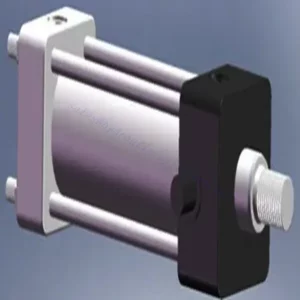
• Pilot-operated two-stage proportional directional valve, used to control the size and direction of the liquid flow
• Threaded connection type proportional solenoid, the coil can be disassembled separately
• Sub-plate mounting connection structure, connection size conforms to DIN2430 and ISO4401 standards
• Justering af spolefjedre
• WRZE type with integrated proportional amplifierr
• WRZ type external amplifier (order separately)
Usage Method Of 4WRZ/H(E) Series Pilot Operated Proportional Directional Hydraulic Valve:
- Systemevaluering
- Evaluer dit hydrauliske system, og identificer de specifikke krav til flow- og retningsstyring.
- Determine if the 4WRZ/H(E) series valve is suitable based on its flow capacity, pressure rating, and compatibility with your system.
- Valg af ventil
- Select the appropriate variant of the 4WRZ/H(E) series valve based on your system parameters, flow requirements, and directional control needs.
- Overvej faktorer som maksimal flowhastighed, trykklassificering, reaktionstid og driftsforhold.
- Installation
- Følg producentens installationsvejledning omhyggeligt, og sørg for korrekt justering og sikker montering af ventilen.
- Sørg for lækagefri forbindelser, og sørg for korrekt justering af strømningsretningen for at garantere optimal ydeevne.
- Tilslutning af styresignal
- Tilslut ventilens styresignalledninger til en passende styreenhed, såsom en proportionalforstærker eller elektronisk styreenhed.
- Sørg for korrekt ledningsføring og kompatibilitet mellem ventilen og styreenheden for at opnå præcis og responsiv styring.
How To Bleed Hydraulic Control Valve?
Bleeding a hydraulic control valve is an essential maintenance procedure to remove any trapped air or gas from the system, ensuring optimal performance and efficiency. Here’s a step-by-step guide on how to bleed a hydraulic control valve:
- Forbered systemet:
- Ensure that the hydraulic system is turned off and that the pressure is relieved. This step is crucial for your safety and to prevent any accidental movement or release of high-pressure fluids.
- Locate the bleeder valve or bleed screw on the hydraulic control valve. It is typically located on the top or side of the valve body and may have a protective cap or cover.
- Positioning and Safety Measures:
- Place a suitable container or absorbent material beneath the bleed valve to catch any fluid that may be expelled during the bleeding process.
- Wear appropriate personal protective equipment (PPE), such as safety goggles and gloves, to protect yourself from hydraulic fluid splashes.
- Opening the Bleed Valve:
- Using an appropriate wrench or tool, carefully loosen the bleed valve or screw counterclockwise. Be cautious not to fully remove it at this stage.
- The bleed valve may have an O-ring or sealing washer. Take note of its position and ensure it is in good condition.
- System Activation:
- Activate the hydraulic system by turning on the power source, such as an engine or hydraulic pump.
- Operate the control mechanism associated with the hydraulic control valve, such as a joystick or lever, to allow fluid flow through the valve.
- Bleeding Process:
- Slowly open the bleed valve by turning it counterclockwise until you start to see hydraulic fluid or air bubbles escaping from the valve.
- Allow the fluid to flow for a few seconds or until you observe a steady stream of fluid without any air bubbles. This indicates that the air has been purged from the system.
- Be cautious not to open the bleed valve too much, as it may lead to excessive fluid loss or system damage.
- Closing the Bleed Valve:
- Once you have successfully bled the system, close the bleed valve by turning it clockwise. Ensure it is tightened securely but avoid over-tightening.
- Check for any leaks around the bleed valve or other connections. If you notice any leaks, address them promptly to prevent further issues.
- System Check:
- Turn off the hydraulic system and inspect the fluid level in the reservoir. Add hydraulic fluid as necessary to maintain the recommended level.
- Test the operation of the hydraulic control valve and associated components to ensure proper functionality.
Fabrikkens kapacitet og kapacitet:
(1) Samling
Vi har en førsteklasses uafhængig forsknings- og udviklingsplatform til montering. Værkstedet for produktion af hydrauliske cylindre har fire halvautomatiske løftecylindermonteringslinjer og en automatisk vippecylindermonteringslinje med en designmæssig årlig produktionskapacitet på 1 million enheder. Det specielle cylinderværksted er udstyret med forskellige specifikationer for et halvautomatisk rengøringsmonteringssystem med en designmæssig årlig produktionskapacitet på 200.000 og udstyret med berømt CNC-bearbejdningsudstyr, et bearbejdningscenter, et specialudstyr til højpræcisionscylinderbearbejdning, en robotsvejsemaskine, en automatisk rengøringsmaskine, en automatisk cylindermonteringsmaskine og en automatisk malingslinje. Eksisterende kritisk udstyr på mere end 300 sæt (sæt). Optimal allokering og effektiv udnyttelse af udstyrsressourcer sikrer produkternes nøjagtighedskrav og opfylder produkternes høje kvalitetsbehov.


(2) Maskinbearbejdning
Bearbejdningsværkstedet er udstyret med et specialfremstillet drejecenter til skrå skinner, bearbejdningscenter, højhastigheds-honemaskine, svejserobot og andet relateret udstyr, der kan håndtere bearbejdning af cylinderrør med en maksimal indre diameter på 400 mm og en maksimal længde på 6 meter.

(3) Svejsning

(4) Maling og overfladebehandling
Med små og mellemstore cylindriske automatiske vandbaserede malingsbelægningslinjer, for at opnå automatisk robotpåfyldning og -aflæsning samt automatisk sprøjtning, er den designmæssige kapacitet på 4000 stykker pr. skift;
Vi har også en halvautomatisk malingsproduktionslinje til store cylindre drevet af en kabelkæde med en designkapacitet på 60 kasser pr. skift.


(5) Testning
Vi har førsteklasses inspektionsfaciliteter og testbænke for at sikre, at cylinderens ydeevne opfylder kravene.

Vi er en af de bedste producenter af hydrauliske cylindre. Vi kan tilbyde et omfattende udvalg af hydrauliske cylindre. Vi leverer også tilsvarende landbrugsgearkasserVi har eksporteret vores produkter til kunder over hele verden og har opnået et godt omdømme på grund af vores overlegne produktkvalitet og eftersalgsservice. Vi byder kunder i ind- og udland velkommen til at kontakte os for at forhandle forretninger, udveksle information og samarbejde med os!