Z2FRM-seriens flowkontrolhydrauliske ventil
Z2FRM-seriens flowkontrolhydrauliske ventil
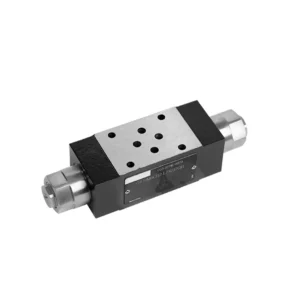
The Z2FRM series flow control hydraulic valve is a state-of-the-art hydraulic component designed to revolutionize the control and efficiency of hydraulic systems. With its advanced features and exceptional performance, this valve provides precise flow control and enhances the overall productivity of hydraulic machinery.
The Z2FRM series flow control hydraulic valve is a game-changing solution for precise flow control in hydraulic systems. With its unmatched precision, versatility, and durability, this valve empowers operators to optimize the performance and efficiency of their hydraulic machinery. By following the recommended usage methods and maintenance guidelines, you can unlock the full potential of the Z2FRM series flow control hydraulic valve, ensuring seamless operation and reliable flow control in your hydraulic applications. Upgrade your hydraulic system today and experience the power of precise hydraulic control with the Z2FRM series valve.
Z2FRM Series Flow Control Hydraulic Valve Key Characteristics:
- Præcisionsflowkontrol:
- The Z2FRM series valve offers unparalleled precision in controlling the flow rate of hydraulic fluids, allowing for fine-tuned adjustments and optimized performance.
- With its high accuracy, this valve ensures consistent flow control, resulting in enhanced system efficiency and improved productivity.
- Alsidige anvendelser:
- The Z2FRM series valve is highly versatile and compatible with a wide range of hydraulic systems, including industrial machinery, construction equipment, and mobile applications.
- Its adaptability makes it an ideal choice for diverse hydraulic setups, providing reliable and efficient flow control.
- Tryk- og temperaturstabilitet:
- Engineered to withstand varying pressure and temperature conditions, the Z2FRM series valve maintains stable flow control even in demanding operational environments.
- It ensures consistent performance, minimizes flow fluctuations, and safeguards the integrity of the hydraulic system.
- Robust konstruktion:
- The Z2FRM Series Valve boasts a robust design and is crafted from high-quality materials, guaranteeing durability and long-lasting reliability.
- Its sturdy construction enables it to withstand high pressures, vibrations, and extreme temperatures, making it a dependable solution for critical hydraulic applications.
Z2FRM Series Flow Control Hydraulic Valve Parameter:
NG6
| Flowkontrolventil | |||||||||||
| Maks. driftstryk - Port A | bar | 315 | |||||||||
| Trykforskel ΔP for fri returstrøm B til A | Se karakteristiske kurver | ||||||||||
| Minimum trykforskel | bar | 6 til 14 | |||||||||
| Trykstabilitet op til P= 315 bar | % | ±2(Qmax) | |||||||||
| Flyde | Qmax | l/min | 0.2 | 0.6 | 1.5 | 3 | 6 | 10 | 16 | 25 | 32 |
| Qmin til 100 bar | ml/min | 15 | 15 | 15 | 15 | 25 | 50 | 70 | 100 | 250 | |
| Qmin til 315 bar | 25 | 25 | 25 | 25 | 25 | 50 | 70 | 100 | 250 | ||
| Væske | Mineralolie, fosfatester | ||||||||||
| Væsketemperaturområde | ℃ | – 20 til + 80 | |||||||||
| Viskositetsområde | mm²/s | 10 til 800 | |||||||||
| Grad af forurening | Maksimal tilladt grad af væskeforurening: Klasse 9. NAS 1638 eller 20/18/15, ISO4406 | ||||||||||
| Installationsposition | Valgfri | ||||||||||
| Omstændigheder temperaturområde | ℃ | -20 til +50 | |||||||||
| Vægt | 2FRM6A…2FRM6B… | kg | omkring 1,3 | ||||||||
| 2FRM6SB… | kg | omkring 1,5 | |||||||||
| Ensretter | |||||||||||
| Nominel strømning | bar | 320 | |||||||||
| Maks. driftstryk | bar | til 210 | |||||||||
| Revnetryk | bar | 0.7 | |||||||||
| Vægt | kg | omkring 0,9 | |||||||||
NG5/10/16
| Flowkontrolventil | ||||||||||||||||
| Maks. driftstryk - Port A | bar | 315 | ||||||||||||||
| Trykforskel ΔP for fri returstrøm B til A | Se karakteristiske kurver | |||||||||||||||
| Minimum trykforskel | bar | 6 til 14 | ||||||||||||||
| Væske | Mineralolie, fosfatester | |||||||||||||||
| Væsketemperaturområde | ℃ | – 20 til + 80 | ||||||||||||||
| Viskositetsområde | mm²/s | 10 til 800 | ||||||||||||||
| Grad af forurening | Maksimal tilladt grad af væskeforurening: Klasse 9. NAS 1638 eller 20/18/15, ISO4406 | |||||||||||||||
| Størrelse | mm | 5 | 10 | 16 | ||||||||||||
| Maks. flowhastighed | l/min | 0.2 | 0.6 | 1.2 | 3 | 6 | 10 | 15 | 10 | 16 | 25 | 50 | 60 | 100 | 160 | |
| Oliereturstrøm B til A | ml/min | 0.5 | 0.5 | 0.6 | 0.9 | 1.8 | 3.6 | 6.7 | 2 | 2.5 | 3.5 | 6 | 2.8 | 4.3 | 7.3 | |
| flowstabilt område (%Qmax) (-20-±80 ℃) | ±5 | ±3 | ±2 | ±2 | ||||||||||||
| ±2 (P=210 bar) | ±2 (P=350 bar) | |||||||||||||||
| Arbejdstryk | bar | 210 | 350 | |||||||||||||
| Min. tryknedsænkning | bar | 3-5 | 6-8 | 3-7 | 5-12 | |||||||||||
| Vægt | kg | 1.6 | 3.4 | 7.4 | ||||||||||||
| Ensretter | ||||||||||||||||
| Væske | Mineralolie, fosfatester | |||||||||||||||
| Væsketemperaturområde | -20 til +80 | |||||||||||||||
| Viskositetsområde | 10 til 800 | |||||||||||||||
| Grad af forurening | Maksimal tilladt grad af væskeforurening: Klasse 9. NAS 1638 eller 20/18/15, ISO4406 | |||||||||||||||
| Størrelse | 5 | 10 | 16 | |||||||||||||
| Flyde | 15 | 50 | 160 | |||||||||||||
| Arbejdstryk | 210 | 315 | 315 | |||||||||||||
| Revnetryk | 1 | 1.5 | 1.5 | |||||||||||||
| Vægt | 0.6 | 3.2 | 9.3 | |||||||||||||
Z2FRM Series Flow Control Hydraulic Valve Advantages:
• Montering af bundplade, se produktkatalog
• Trykkompenserende forskydningsbegrænser, valgfri
• Valgfri envejsventil
• Knap med skala, valgfri låsbarhed
Usage Method Of Z2FRM Series Flow Control Hydraulic Valve:
- Systemevaluering:
- Begin by assessing the specific requirements of your hydraulic system, including desired flow rates, pressure ranges, and flow control parameters.
- Determine if the Z2FRM series valve suits your application based on its flow control capabilities and compatibility with your system.
- Valg af ventil:
- Select the appropriate variant of the Z2FRM series valve based on your system parameters, desired flow rate, and compatibility with other system components.
- Overvej faktorer som maksimal flowkapacitet, trykklassificering og driftsforhold.
- Installation:
- Follow the manufacturer’s installation instructions meticulously, ensuring precise alignment and secure valve connections.
- Pay close attention to the flow direction indicators, ensuring the correct positioning of the valve within the hydraulic system.
- Justering af flowkontrol:
- Once installed, adjust the flow control settings of the valve to achieve the desired flow rate and meet your system requirements.
- Fine-tune the valve to optimize the speed and performance of hydraulic actuators, thereby maximizing overall system efficiency.
Hvordan tilføjer man en hydraulisk ventil til en traktor?
Adding a hydraulic valve to a tractor can expand its functionality and enable the use of hydraulic attachments and implements. Here are the general steps to follow when adding a hydraulic valve to a tractor:
- Determine the Tractor’s Hydraulic System:
- Check if your tractor already has a hydraulic system in place. Many modern tractors come equipped with hydraulic systems, while older models may require modifications or additional components.
- Choose the Right Hydraulic Valve:
- Select a hydraulic valve that suits your specific needs and requirements. Consider factors such as flow rate, pressure rating, number of spools, and compatibility with your tractor’s hydraulic system.
- Saml de nødvendige værktøjer og materialer:
- Ensure you have all the required tools and materials for the installation process. This may include wrenches, hydraulic hoses, fittings, mounting brackets, and the hydraulic valve itself.
- Identify the Installation Location:
- Determine the ideal location for mounting the hydraulic valve on your tractor. This is typically near the existing hydraulic ports or in a convenient and accessible position.
- Prepare the Tractor:
- Before installation, shut off the tractor’s engine and relieve any pressure in the hydraulic system by moving the hydraulic control levers back and forth.
- Install the Hydraulic Valve:
- Mount the hydraulic valve securely using the appropriate brackets or mounting hardware. Ensure it is positioned correctly and aligned with the hydraulic ports.
- Connect the Hydraulic Hoses:
- Attach hydraulic hoses to the valve’s ports, ensuring a secure connection. Use appropriate fittings and tighten them properly to prevent leaks.
- Connect to the Tractor’s Hydraulic System:
- Identify the tractor’s existing hydraulic ports or couplers. Connect the hydraulic hoses from the valve to these ports, matching the appropriate fittings.
- Test for Leaks:
- Once all connections are made, start the tractor’s engine and operate the hydraulic controls. Carefully inspect all connections for any signs of hydraulic fluid leaks. Address any leaks promptly by tightening fittings or replacing damaged components.
- Test the Hydraulic Valve:
- Engage the hydraulic controls and test the operation of the newly installed hydraulic valve. Ensure that it functions smoothly and controls the hydraulic attachments as intended.
- Secure and Protect the Hoses:
- Secure the hydraulic hoses in place using clamps or brackets to prevent them from interfering with other tractor components or getting damaged during operation. Consider using protective covers for the hoses to safeguard them from environmental elements and potential abrasion.
Fabrikkens kapacitet og kapacitet:
(1) Samling
Vi har en førsteklasses uafhængig forsknings- og udviklingsplatform til montering. Værkstedet for produktion af hydrauliske cylindre har fire halvautomatiske løftecylindermonteringslinjer og en automatisk vippecylindermonteringslinje med en designmæssig årlig produktionskapacitet på 1 million enheder. Det specielle cylinderværksted er udstyret med forskellige specifikationer for et halvautomatisk rengøringsmonteringssystem med en designmæssig årlig produktionskapacitet på 200.000 og udstyret med berømt CNC-bearbejdningsudstyr, et bearbejdningscenter, et specialudstyr til højpræcisionscylinderbearbejdning, en robotsvejsemaskine, en automatisk rengøringsmaskine, en automatisk cylindermonteringsmaskine og en automatisk malingslinje. Eksisterende kritisk udstyr på mere end 300 sæt (sæt). Optimal allokering og effektiv udnyttelse af udstyrsressourcer sikrer produkternes nøjagtighedskrav og opfylder produkternes høje kvalitetsbehov.


(2) Maskinbearbejdning
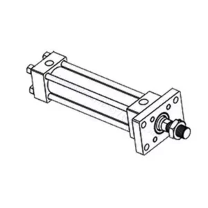
Bearbejdningsværkstedet er udstyret med et specialfremstillet drejecenter til skrå skinner, bearbejdningscenter, højhastigheds-honemaskine, svejserobot og andet relateret udstyr, der kan håndtere bearbejdning af cylinderrør med en maksimal indre diameter på 400 mm og en maksimal længde på 6 meter.

(3) Svejsning

(4) Maling og overfladebehandling
Med små og mellemstore cylindriske automatiske vandbaserede malingsbelægningslinjer, for at opnå automatisk robotpåfyldning og -aflæsning samt automatisk sprøjtning, er den designmæssige kapacitet på 4000 stykker pr. skift;
Vi har også en halvautomatisk malingsproduktionslinje til store cylindre drevet af en kabelkæde med en designkapacitet på 60 kasser pr. skift.


(5) Testning
Vi har førsteklasses inspektionsfaciliteter og testbænke for at sikre, at cylinderens ydeevne opfylder kravene.

Vi er en af de bedste producenter af hydrauliske cylindre. Vi kan tilbyde et omfattende udvalg af hydrauliske cylindre. Vi leverer også tilsvarende landbrugsgearkasserVi har eksporteret vores produkter til kunder over hele verden og har opnået et godt omdømme på grund af vores overlegne produktkvalitet og eftersalgsservice. Vi byder kunder i ind- og udland velkommen til at kontakte os for at forhandle forretninger, udveksle information og samarbejde med os!