Σειρά 4WRKE με αναλογική κατευθυντική υδραυλική βαλβίδα με πιλότο
Σειρά 4WRKE με αναλογική κατευθυντική υδραυλική βαλβίδα με πιλότο
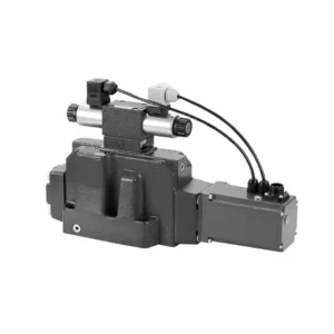
The 4WRKE series pilot-operated proportional directional hydraulic valve is a cutting-edge hydraulic component designed to provide superior precision, control, and efficiency in hydraulic systems. With its advanced pilot-operated proportional control technology, this valve enables accurate flow regulation and seamless directional changes.
The 4WRKE series pilot-operated proportional directional hydraulic valve empowers hydraulic systems with precise flow control, versatile directional changes, and energy efficiency. Its pilot-operated proportional control technology ensures accurate and responsive flow adjustment, while the high flow capacity guarantees reliable performance even in demanding applications. By following the recommended usage methods and maintenance guidelines, you can maximize the benefits and longevity of the 4WRKE series valve, elevating your hydraulic system to new levels of precision and control. Upgrade your hydraulic setup today and experience the power of the 4wrke series pilot-operated proportional directional hydraulic valve.
4WRKE Series Pilot Operated Proportional Directional Hydraulic Valve Key Characteristics:
- Pilot-Operated Proportional Control
- The 4WRKE series valve utilizes pilot-operated proportional control technology, allowing precise and proportional flow adjustment based on control signals.
- Αυτή η λειτουργία διασφαλίζει ακριβή και γρήγορο έλεγχο, με αποτέλεσμα βελτιωμένη απόδοση του συστήματος, μειωμένη κατανάλωση ενέργειας και αυξημένη παραγωγικότητα.
- Versatile Directional Control
- Αυτή η βαλβίδα προσφέρει ευέλικτο έλεγχο της κατεύθυνσης του υδραυλικού υγρού, καθιστώντας την κατάλληλη για ένα ευρύ φάσμα εφαρμογών.
- Επιτρέπει την απρόσκοπτη ενεργοποίηση και απενεργοποίηση υδραυλικών εξαρτημάτων όπως κυλίνδρους, κινητήρες και ενεργοποιητές σε διαφορετικές κατευθύνσεις, ενισχύοντας την ευελιξία και την προσαρμοστικότητα του συστήματος.
- High Flow Capacity
- The 4WRKE series valve is engineered to handle high flow rates, making it ideal for applications that require substantial hydraulic power.
- Η στιβαρή κατασκευή του εξασφαλίζει αξιόπιστη απόδοση ακόμη και υπό απαιτητικές συνθήκες, παρέχοντας συνεπή και αποτελεσματικό έλεγχο ροής.
- Ενεργειακή Απόδοση
- By incorporating pilot-operated proportional control, this valve minimizes pressure drops and optimizes energy usage.
- Βοηθά στη μείωση της κατανάλωσης ενέργειας, με αποτέλεσμα εξοικονόμηση κόστους και περιβαλλοντικά οφέλη.
4WRKE Series Pilot Operated Proportional Directional Hydraulic Valve Parameter:
| Γενικός | |||||||||
| Μέγεθος | 10 | 16 | 25 | 27 | 32 | 35 | |||
| Installation and commissioning guidelines | προαιρετικά, κατά προτίμηση οριζόντια | ||||||||
| Storage temperature range | ℃ | – 20 to + 80 | |||||||
| Εύρος θερμοκρασίας περιβάλλοντος | ℃ | -20 to + 50 | |||||||
| Βάρος | κιλά | 8.7 | 11.2 | 16.8 | 20 | 37.2 | 72 | ||
| Υδραυλικός ( measured at p=100bar,with HLP46 at ϑoil =40℃ ±5℃) | |||||||||
| Πίεση λειτουργίας | -Pilot control valve | Pilot oil supply | μπαρ | 25 to 315 | |||||
| -Main valve | Port P A B | μπαρ | Up to 315 | Up to 350 | Up to 350 | Up to 210 | Up to 350 | Up to 350 | |
| Return pressure | Λιμάνι Τ
(Pilot oil drain) |
Internal | μπαρ | Static < 10 | |||||
| External | μπαρ | Up to 315 | Up to 250 | Up to 250 | Up to 210 | Up to 250 | Up to 250 | ||
| Λιμάνι Υ | μπαρ | Static < 10 | |||||||
| Nominal flow qVnom ±10% at Δp=10bar (Δp = valve pressure differential) |
Λ/λεπτό | 25 50 | – 125 | – 220 | – – | – 440 | – | ||
| 100 | 180 | 350 | 500 | 600 | 1000 | ||||
| Flow of main valve (max. permissible) | Λ/λεπτό | 170 | 460 | 870 | 1000 | 1600 | 3000 | ||
| Pilot oil flow at port X or Y with a step form of input signal from 0 to 100 % (315 bar) | Λ/λεπτό | 4.1 | 8.5 | 11.7 | 11.7 | 13 | 13 | ||
| Ρευστό υπό πίεση | Mineral oil(HL,HLP)to DIN 51 524 Phosphate ester (HFD-R) | ||||||||
| Εύρος θερμοκρασίας ρευστού | ℃ | 10 to 80, preferably 40 to 50 | |||||||
| Εύρος ιξώδους | χιλ.2/μικρό | 20 to 380, preferably 30 to 45 | |||||||
| Βαθμός μόλυνσης | Maximum permissible degree of contamination: NAS 1638. | A filter with a minimum retention rate of βx = 75 is recommended | |||||||
| Pilot control valve | Class 7 | x = 5 | |||||||
| Main valve | Class 9 | x = 7 | |||||||
| Υστέρηση | % | ≤1 | |||||||
| Ευαισθησία απόκρισης | % | ≤0,5 | |||||||
| Electrical | |||||||||
| Τύπος τάσης | Ουάσινγκτον | ||||||||
| Electrical connection | Plug-in connector to DIN EN175 201-804 | ||||||||
| Power, max. | W | 72 (average = 24W) | |||||||
| Control electronics | Integrated into the valve | ||||||||
4WRKE Series Pilot Operated Proportional Directional Hydraulic Valve Advantages:
• Pilot-operated two-stage proportional directional valve with electrical position feedback of the main spool, used to control the size and direction of the liquid flow
• Sub-plate mounting type connection structure, connection size conforms to ISO 4401 standard
• Spring centred main spool
• With integrated proportional amplifier
• The pilot control is a single-stage proportional directional valve
• The pilot valve is a threaded proportional solenoid, and the coil can be disassembled separately
Usage Method Of 4WRKE Series Pilot Operated Proportional Directional Hydraulic Valve:
- System Evaluation
- Αξιολογήστε το υδραυλικό σας σύστημα και προσδιορίστε τις συγκεκριμένες απαιτήσεις ελέγχου ροής και κατεύθυνσης.
- Determine if the 4WRKE Series Valve is suitable based on its flow capacity, pressure rating, and compatibility with your system.
- Valve Selection
- Select the appropriate variant of the 4WRKE Series Valve based on your system parameters, flow requirements, and directional control needs.
- Λάβετε υπόψη παράγοντες όπως η μέγιστη παροχή, η ονομαστική πίεση, ο χρόνος απόκρισης και οι συνθήκες λειτουργίας.
- Εγκατάσταση
- Ακολουθήστε προσεκτικά τις οδηγίες εγκατάστασης του κατασκευαστή, διασφαλίζοντας την σωστή ευθυγράμμιση και την ασφαλή τοποθέτηση της βαλβίδας.
- Make leak-free connections and ensure the correct flow direction alignment to guarantee optimal performance.
- Control Signal Connection
- Συνδέστε τα καλώδια σήματος ελέγχου της βαλβίδας σε μια κατάλληλη συσκευή ελέγχου, όπως έναν αναλογικό ενισχυτή ή μια ηλεκτρονική μονάδα ελέγχου.
- Βεβαιωθείτε για την σωστή καλωδίωση και συμβατότητα μεταξύ της βαλβίδας και της συσκευής ελέγχου για ακριβή και άμεσο έλεγχο.
How To Clean Hydraulic Valve Lifters?
Cleaning hydraulic valve lifters is an important maintenance task that helps ensure proper engine performance and reduce noise caused by dirt or debris buildup. Here’s a step-by-step guide on how to clean hydraulic valve lifters:
- Συγκεντρώστε τα απαραίτητα εργαλεία και υλικά:
- New engine oil
- Clean rags or towels
- Engine degreaser or parts cleaner
- Small brush or toothbrush
- Plastic container or tray
- Παρασκευή:
- Allow the engine to cool down completely before starting the cleaning process.
- Remove the valve cover or covers to access the hydraulic valve lifters. Refer to the manufacturer’s instructions or a repair manual for your specific engine to locate and remove the valve cover(s) properly.
- Removal of Hydraulic Valve Lifters:
- Identify the hydraulic valve lifters in the engine.
- One at a time, carefully remove the hydraulic valve lifters from their respective locations. Depending on your engine, you may need to remove other components or parts to access the lifters.
- Place each lifter in a plastic container or tray in the order they were removed. This will help ensure they are reinstalled correctly later.
- Cleaning the Lifters:
- Pour a small amount of engine degreaser or parts cleaner into a container.
- Place one hydraulic valve lifter into the container, ensuring it is fully submerged in the cleaner.
- Allow the lifter to soak for the recommended duration specified by the cleaner manufacturer. This usually ranges from 15 minutes to an hour.
- Use a small brush or toothbrush to gently scrub the lifter’s exterior surfaces, removing any deposits or dirt.
- Rinse the lifter thoroughly with clean water to remove any remaining cleaner or debris.
- Dry the lifter using a clean rag or towel. Ensure there are no traces of moisture before reinstallation.
- Reinstallation:
- Apply a small amount of fresh engine oil to the cleaned lifter’s exterior surface.
- Carefully place the lifter back into its original position in the engine, ensuring it is properly aligned and seated.
- Repeat the cleaning process for each hydraulic valve lifter, following the same steps.
- Once all the lifters are cleaned and reinstalled, make sure they are secured properly.
- Επανασυναρμολόγηση:
- Reinstall the valve cover(s) according to the manufacturer’s instructions.
- Double-check that all components and parts are properly secured and tightened.
- Test and Inspection:
- Start the engine and let it run for a few minutes to ensure proper operation and to allow the lifters to refill with oil.
- Listen for any abnormal noises or ticking sounds that could indicate further issues.
- If noise or performance problems persist, it may be necessary to consult a professional mechanic for further diagnosis and repair.
Ικανότητα & χωρητικότητα του εργοστασίου:
(1) Συναρμολόγηση
Διαθέτουμε μια πρώτης τάξεως ανεξάρτητη πλατφόρμα συναρμολόγησης έρευνας και ανάπτυξης. Το εργαστήριο παραγωγής υδραυλικών κυλίνδρων διαθέτει τέσσερις ημιαυτόματες γραμμές συναρμολόγησης ανυψωτικών κυλίνδρων και μία αυτόματη γραμμή συναρμολόγησης κυλίνδρων κλίσης, με σχεδιασμένη ετήσια παραγωγική ικανότητα 1 εκατομμυρίου τεμαχίων. Το εργαστήριο ειδικών κυλίνδρων είναι εξοπλισμένο με διάφορες προδιαγραφές ενός ημιαυτόματου συστήματος συναρμολόγησης καθαρισμού με σχεδιασμένη ετήσια παραγωγική ικανότητα 200.000 και εξοπλισμένο με διάσημο εξοπλισμό κατεργασίας CNC, ένα κέντρο κατεργασίας, έναν ειδικό εξοπλισμό επεξεργασίας κυλίνδρων υψηλής ακρίβειας, μια μηχανή συγκόλλησης ρομπότ, μια αυτόματη μηχανή καθαρισμού, μια αυτόματη μηχανή συναρμολόγησης κυλίνδρων και μια αυτόματη γραμμή παραγωγής βαφής. Υφιστάμενος κρίσιμος εξοπλισμός άνω των 300 σετ (σετ). Η βέλτιστη κατανομή και η αποτελεσματική χρήση των πόρων του εξοπλισμού διασφαλίζουν τις απαιτήσεις ακρίβειας των προϊόντων και καλύπτουν τις ανάγκες υψηλής ποιότητας των προϊόντων.


(2) Κατεργασία
Το εργαστήριο κατεργασίας είναι εξοπλισμένο με ένα προσαρμοσμένο κέντρο τόρνευσης με κεκλιμένη ράγα, κέντρο κατεργασίας, μηχανή λείανσης υψηλής ταχύτητας, ρομπότ συγκόλλησης και άλλο συναφή εξοπλισμό, το οποίο μπορεί να χειριστεί την επεξεργασία κυλινδρικών σωλήνων με μέγιστη εσωτερική διάμετρο 400 mm και μέγιστο μήκος 6 μέτρων.

(3) Συγκόλληση

(4) Βαφή και επίστρωση
Με μικρές και μεσαίες αυτόματες γραμμές επίστρωσης χρωμάτων με βάση το νερό, για την επίτευξη αυτόματης φόρτωσης και εκφόρτωσης ρομπότ και αυτόματου ψεκασμού, η ικανότητα σχεδιασμού 4000 τεμαχίων ανά βάρδια,
Διαθέτουμε επίσης μια ημιαυτόματη γραμμή παραγωγής χρωμάτων για μεγάλους κυλίνδρους που τροφοδοτείται από μια αλυσίδα ισχύος, με δυνατότητα σχεδιασμού 60 κιβωτίων ανά βάρδια.


(5) Δοκιμές
Διαθέτουμε πρώτης τάξεως εγκαταστάσεις επιθεώρησης και δοκιμαστικές κλίνες για να διασφαλίσουμε ότι η απόδοση του κυλίνδρου ανταποκρίνεται στις απαιτήσεις.

Είμαστε ένας από τους καλύτερους κατασκευαστές υδραυλικών κυλίνδρων. Μπορούμε να προσφέρουμε ολοκληρωμένους υδραυλικούς κυλίνδρους. Παρέχουμε επίσης αντίστοιχους γεωργικά κιβώτια ταχυτήτων. Έχουμε εξάγει τα προϊόντα μας σε πελάτες σε όλο τον κόσμο και έχουμε κερδίσει μια καλή φήμη λόγω της ανώτερης ποιότητας των προϊόντων μας και της εξυπηρέτησης μετά την πώληση. Καλωσορίζουμε τους πελάτες στο εσωτερικό και στο εξωτερικό να επικοινωνήσουν μαζί μας για να διαπραγματευτούν τις επιχειρήσεις, να ανταλλάξουν πληροφορίες και να συνεργαστείτε μαζί μας!