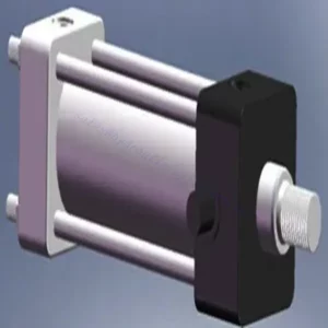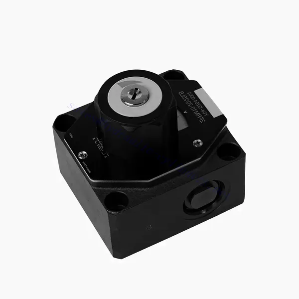
Υδραυλική βαλβίδα ελέγχου ροής σειράς FRM
Υδραυλική βαλβίδα ελέγχου ροής σειράς FRM
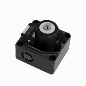
Η υδραυλική βαλβίδα ελέγχου ροής της σειράς FRM είναι ένα υδραυλικό εξάρτημα αιχμής που έχει σχεδιαστεί για να βελτιώνει την απόδοση και τον έλεγχο των υδραυλικών συστημάτων. Με τα προηγμένα χαρακτηριστικά και την αξιόπιστη λειτουργικότητά της, αυτή η βαλβίδα προσφέρει ακριβή έλεγχο ροής και βέλτιστη απόδοση.
Η υδραυλική βαλβίδα ελέγχου ροής της σειράς FRM είναι μια αξιόπιστη και ευέλικτη λύση για τη βελτιστοποίηση του ελέγχου ροής σε υδραυλικά συστήματα. Με τις δυνατότητες ακριβούς ελέγχου ροής, τη σταθερότητα πίεσης και θερμοκρασίας και την ανθεκτική κατασκευή, αυτή η βαλβίδα προσφέρει βελτιωμένη απόδοση και αποδοτικότητα. Ακολουθώντας τις συνιστώμενες μεθόδους χρήσης και τις οδηγίες συντήρησης, οι χειριστές μπορούν να μεγιστοποιήσουν τα οφέλη της υδραυλικής βαλβίδας ελέγχου ροής της σειράς FRM, εξασφαλίζοντας ομαλή λειτουργία και αξιόπιστο έλεγχο ροής στις υδραυλικές εφαρμογές τους. Αναβαθμίστε το υδραυλικό σας σύστημα με αυτήν την προηγμένη βαλβίδα και ζήστε ακρίβεια, αποδοτικότητα και παραγωγικότητα όπως ποτέ άλλοτε.
Βασικά χαρακτηριστικά υδραυλικής βαλβίδας ελέγχου ροής σειράς FRM:
- Ακρίβεια ελέγχου ροής:
- Η βαλβίδα της σειράς FRM επιτρέπει τον ακριβή έλεγχο της ροής των υδραυλικών υγρών, επιτρέποντας στους χειριστές να ρυθμίζουν με ακρίβεια την ταχύτητα των ενεργοποιητών.
- Με την εξαιρετική της ακρίβεια, αυτή η βαλβίδα εξασφαλίζει συνεπή έλεγχο ροής, με αποτέλεσμα βελτιωμένη απόδοση του συστήματος και αυξημένη παραγωγικότητα.
- Ευέλικτη εφαρμογή:
- Η βαλβίδα της σειράς FRM είναι εξαιρετικά ευέλικτη και συμβατή με διάφορα υδραυλικά συστήματα, συμπεριλαμβανομένων βιομηχανικών μηχανημάτων, εξοπλισμού κατασκευών και κινητών εφαρμογών.
- Η προσαρμοστικότητά του το καθιστά ιδανική επιλογή για ένα ευρύ φάσμα υδραυλικών διατάξεων, παρέχοντας αξιόπιστο και αποτελεσματικό έλεγχο ροής.
- Σταθερότητα πίεσης και θερμοκρασίας:
- Αυτή η υδραυλική βαλβίδα έχει σχεδιαστεί για να διατηρεί σταθερό έλεγχο ροής ακόμη και υπό μεταβαλλόμενες συνθήκες πίεσης και θερμοκρασίας.
- Εξασφαλίζει σταθερή απόδοση και αποτρέπει τις διακυμάνσεις της ροής, διασφαλίζοντας την ακεραιότητα και την αξιοπιστία του υδραυλικού συστήματος.
- Ανθεκτική κατασκευή:
- Η βαλβίδα της σειράς FRM κατασκευάζεται με υλικά υψηλής ποιότητας, εξασφαλίζοντας ανθεκτικότητα και μακροπρόθεσμη αξιοπιστία σε απαιτητικά περιβάλλοντα λειτουργίας.
- Ο στιβαρός σχεδιασμός του επιτρέπει να αντέχει σε υψηλές πιέσεις, κραδασμούς και ακραίες θερμοκρασίες, παρέχοντας μια αξιόπιστη λύση για υδραυλικές εφαρμογές.
Παράμετρος υδραυλικής βαλβίδας ελέγχου ροής σειράς FRM:
NG6
| Βαλβίδα ελέγχου ροής | |||||||||||
| Μέγιστη λειτουργούσα πίεση-Θύρα Α | μπαρ | 315 | |||||||||
| Διαφορική πίεση ΔP για ελεύθερη ροή επιστροφής Β προς Α | Δείτε χαρακτηριστικές καμπύλες | ||||||||||
| Ελάχιστη διαφορά πίεσης | μπαρ | 6 έως 14 | |||||||||
| Σταθερότητα πίεσης έως P= 315 bar | % | ±2 (Qmax) | |||||||||
| Ροή | Qmax | Λ/λεπτό | 0.2 | 0.6 | 1.5 | 3 | 6 | 10 | 16 | 25 | 32 |
| Qmin έως 100bar | mL/λεπτό | 15 | 15 | 15 | 15 | 25 | 50 | 70 | 100 | 250 | |
| Qmin έως 315bar | 25 | 25 | 25 | 25 | 25 | 50 | 70 | 100 | 250 | ||
| Υγρό | Ορυκτέλαιο, φωσφορικός εστέρας | ||||||||||
| Εύρος θερμοκρασίας ρευστού | ℃ | – 20 έως + 80 | |||||||||
| Εύρος ιξώδους | mm2/s | 10 έως 800 | |||||||||
| Βαθμός μόλυνσης | Μέγιστος επιτρεπόμενος βαθμός μόλυνσης υγρού: Κλάση 9. NAS 1638 ή 20/18/15, ISO4406 | ||||||||||
| Θέση εγκατάστασης | Προαιρετικός | ||||||||||
| Εύρος θερμοκρασίας περιστάσεων | ℃ | -20 έως +50 | |||||||||
| Βάρος | 2FRM6A…2FRM6B… | κιλά | περίπου 1,3 | ||||||||
| 2FRM6SB… | κιλά | περίπου 1,5 | |||||||||
| Διορθωτής | |||||||||||
| Ονομαστική ροή | μπαρ | 320 | |||||||||
| Μέγιστη λειτουργούσα πίεση | μπαρ | έως 210 | |||||||||
| Πίεση ρωγμών | μπαρ | 0.7 | |||||||||
| Βάρος | κιλά | περίπου 0,9 | |||||||||
NG5/10/16
| Βαλβίδα ελέγχου ροής | ||||||||||||||||
| Μέγιστη λειτουργούσα πίεση-Θύρα Α | μπαρ | 315 | ||||||||||||||
| Διαφορική πίεση ΔP για ελεύθερη ροή επιστροφής Β προς Α | Δείτε χαρακτηριστικές καμπύλες | |||||||||||||||
| Ελάχιστη διαφορά πίεσης | μπαρ | 6 έως 14 | ||||||||||||||
| Υγρό | Ορυκτέλαιο, φωσφορικός εστέρας | |||||||||||||||
| Εύρος θερμοκρασίας ρευστού | ℃ | – 20 έως + 80 | ||||||||||||||
| Εύρος ιξώδους | mm2/s | 10 έως 800 | ||||||||||||||
| Βαθμός μόλυνσης | Μέγιστος επιτρεπόμενος βαθμός μόλυνσης υγρού: Κλάση 9. NAS 1638 ή 20/18/15, ISO4406 | |||||||||||||||
| Μέγεθος | χιλ. | 5 | 10 | 16 | ||||||||||||
| Μέγιστος ρυθμός ροής | Λ/λεπτό | 0.2 | 0.6 | 1.2 | 3 | 6 | 10 | 15 | 10 | 16 | 25 | 50 | 60 | 100 | 160 | |
| Ροή επιστροφής λαδιού Β προς Α | mL/λεπτό | 0.5 | 0.5 | 0.6 | 0.9 | 1.8 | 3.6 | 6.7 | 2 | 2.5 | 3.5 | 6 | 2.8 | 4.3 | 7.3 | |
| σταθερό εύρος ροής (%Qmax) (-20-±80℃) | ±5 | ±3 | ±2 | ±2 | ||||||||||||
| ±2 (P=210 bar) | ±2 (P=350 bar) | |||||||||||||||
| Πίεση εργασίας | μπαρ | 210 | 350 | |||||||||||||
| Ελάχιστη πτώση πίεσης | μπαρ | 3-5 | 6-8 | 3-7 | 5-12 | |||||||||||
| Βάρος | κιλά | 1.6 | 3.4 | 7.4 | ||||||||||||
| Διορθωτής | ||||||||||||||||
| Υγρό | Ορυκτέλαιο, φωσφορικός εστέρας | |||||||||||||||
| Εύρος θερμοκρασίας ρευστού | -20 έως +80 | |||||||||||||||
| Εύρος ιξώδους | 10 έως 800 | |||||||||||||||
| Βαθμός μόλυνσης | Μέγιστος επιτρεπόμενος βαθμός μόλυνσης υγρού: Κλάση 9. NAS 1638 ή 20/18/15, ISO4406 | |||||||||||||||
| Μέγεθος | 5 | 10 | 16 | |||||||||||||
| Ροή | 15 | 50 | 160 | |||||||||||||
| Πίεση εργασίας | 210 | 315 | 315 | |||||||||||||
| Πίεση ρωγμών | 1 | 1.5 | 1.5 | |||||||||||||
| Βάρος | 0.6 | 3.2 | 9.3 | |||||||||||||
Πλεονεκτήματα υδραυλικής βαλβίδας ελέγχου ροής σειράς FRM:
• Τοποθέτηση βάσης υποπλάκας, δείτε τον κατάλογο προϊόντων
• Περιοριστής μετατόπισης αντιστάθμισης πίεσης, προαιρετικός
• Προαιρετική βαλβίδα μίας κατεύθυνσης
• Κουμπί με κλίμακα, προαιρετική δυνατότητα κλειδώματος
Μέθοδος χρήσης υδραυλικής βαλβίδας ελέγχου ροής σειράς FRM:
- Αξιολόγηση Συστήματος:
- Ξεκινήστε αξιολογώντας τις απαιτήσεις του υδραυλικού συστήματος, συμπεριλαμβανομένων των ρυθμών ροής, των εύρων πίεσης και των επιθυμητών παραμέτρων ελέγχου ροής.
- Προσδιορίστε εάν η βαλβίδα της σειράς FRM είναι κατάλληλη για τη συγκεκριμένη εφαρμογή με βάση τις δυνατότητες ελέγχου ροής της.
- Επιλογή βαλβίδας:
- Επιλέξτε την κατάλληλη παραλλαγή της βαλβίδας σειράς FRM με βάση τις παραμέτρους του συστήματος, τον επιθυμητό ρυθμό ροής και τη συμβατότητα με άλλα εξαρτήματα του συστήματος.
- Λάβετε υπόψη παράγοντες όπως η μέγιστη χωρητικότητα ροής, η ονομαστική πίεση και οι συνθήκες λειτουργίας.
- Εγκατάσταση:
- Ακολουθήστε προσεκτικά τις οδηγίες εγκατάστασης του κατασκευαστή, διασφαλίζοντας την σωστή ευθυγράμμιση και τις ασφαλείς συνδέσεις των βαλβίδων.
- Δώστε προσοχή στους δείκτες κατεύθυνσης ροής, διασφαλίζοντας τη σωστή τοποθέτηση της βαλβίδας στο υδραυλικό σύστημα.
- Ρύθμιση ελέγχου ροής:
- Μόλις εγκατασταθεί, προσαρμόστε τις ρυθμίσεις ελέγχου ροής της βαλβίδας σύμφωνα με τον επιθυμητό ρυθμό ροής και τις απαιτήσεις του συστήματος.
- Βελτιστοποιήστε τη βαλβίδα για να επιτύχετε την επιθυμητή ταχύτητα και απόδοση των υδραυλικών ενεργοποιητών, βελτιστοποιώντας τη συνολική λειτουργία του συστήματος.
Πώς λειτουργούν οι υδραυλικές βαλβίδες;
Οι υδραυλικές βαλβίδες είναι ζωτικής σημασίας για τον έλεγχο της ροής και της κατεύθυνσης του υδραυλικού υγρού μέσα σε ένα υδραυλικό σύστημα. Είναι απαραίτητα εξαρτήματα που επιτρέπουν την ακριβή λειτουργία διαφόρων υδραυλικών μηχανημάτων και εξοπλισμού. Ακολουθεί μια απλοποιημένη εξήγηση για το πώς λειτουργούν οι υδραυλικές βαλβίδες:
- Βασικά στοιχεία υδραυλικών συστημάτων:
Τα υδραυλικά συστήματα χρησιμοποιούν ρευστό, συνήθως λάδι, για τη μετάδοση ισχύος και τον έλεγχο της κίνησης των μηχανικών εξαρτημάτων. Αυτά τα συστήματα αποτελούνται από μια υδραυλική αντλία που ασκεί πίεση στο υγρό, μια σειρά βαλβίδων που ελέγχουν τη ροή και την κατεύθυνση του ρευστού και υδραυλικούς ενεργοποιητές (όπως κύλινδροι ή κινητήρες) που μετατρέπουν την ενέργεια του ρευστού σε μηχανική δύναμη ή κίνηση. - Τύποι βαλβίδων:
Υπάρχουν διάφορες υδραυλικές βαλβίδες, όπως βαλβίδες κατευθυντικού ελέγχου, βαλβίδες ελέγχου πίεσης, βαλβίδες ελέγχου ροής και βαλβίδες αντεπιστροφής. Κάθε τύπος βαλβίδας εξυπηρετεί έναν συγκεκριμένο σκοπό στη ρύθμιση της ροής, της πίεσης ή της κατεύθυνσης του ρευστού. - Βαλβίδες κατευθυντικού ελέγχου:
Οι βαλβίδες κατευθυντικού ελέγχου καθορίζουν τη διαδρομή μέσω της οποίας ρέει το υδραυλικό υγρό. Έχουν πολλαπλές θέσεις (όπως ανοιχτή, κλειστή ή μερικώς ανοιχτή) και πολλαπλές θύρες για να κατευθύνουν το υγρό σε διαφορετικά τμήματα του υδραυλικού συστήματος. - Στοιχεία βαλβίδας:
Οι υδραυλικές βαλβίδες συνήθως αποτελούνται από ένα σώμα βαλβίδας, το οποίο περιέχει εσωτερικές διόδους και κανάλια, και ένα κινητό στοιχείο βαλβίδας ή καρούλι που ολισθαίνει μέσα στο σώμα της βαλβίδας. Το καρούλι έχει διαφορετικές οπές ή θύρες που ευθυγραμμίζονται με τις εσωτερικές διόδους για τον έλεγχο της ροής του ρευστού. - Κίνηση καρουλιού:
Η θέση του καρουλιού μέσα στο σώμα της βαλβίδας καθορίζει την πορεία ροής και, κατά συνέπεια, την κατεύθυνση ροής του ρευστού. Το καρούλι μπορεί να ενεργοποιηθεί με διάφορα μέσα, όπως μηχανικές συνδέσεις, ηλεκτρομαγνητικά πηνία ή πίεση πιλότου. - Βαλβίδες ελέγχου πίεσης:
Οι βαλβίδες ελέγχου πίεσης ρυθμίζουν την πίεση του υδραυλικού υγρού μέσα στο σύστημα. Μπορούν να διατηρήσουν ένα συγκεκριμένο επίπεδο πίεσης επιτρέποντας στην περίσσεια υγρού να επιστρέψει στη δεξαμενή ή εμποδίζοντας τη ροή μέχρι να επιτευχθεί η επιθυμητή πίεση. - Βαλβίδες ελέγχου ροής:
Οι βαλβίδες ελέγχου ροής διαχειρίζονται τον ρυθμό ροής του ρευστού εντός του υδραυλικού συστήματος. Μπορούν να χρησιμοποιηθούν για τον έλεγχο της ταχύτητας των υδραυλικών ενεργοποιητών ή για τον περιορισμό του ρυθμού ροής σε συγκεκριμένα τμήματα του συστήματος. - Βαλβίδες αντεπιστροφής:
Οι βαλβίδες αντεπιστροφής ή μονόδρομες βαλβίδες επιτρέπουν τη ροή του ρευστού προς μία κατεύθυνση και αποτρέπουν την αντίστροφη ροή. Εξασφαλίζουν ότι το ρευστό κινείται προς την επιθυμητή κατεύθυνση και αποτρέπουν τυχόν ανεπιθύμητες πτώσεις πίεσης ή απώλεια υδραυλικής δύναμης. - Ενεργοποίηση βαλβίδας:
Οι υδραυλικές βαλβίδες μπορούν να λειτουργούν χειροκίνητα, να ενεργοποιούνται μηχανικά ή να ελέγχονται ηλεκτρονικά. Οι μοχλοί ή τα κουμπιά χειρίζονται απευθείας τις χειροκίνητες βαλβίδες, ενώ οι μηχανικοί και ηλεκτρονικοί ενεργοποιητές επιτρέπουν τον αυτοματοποιημένο έλεγχο των θέσεων των βαλβίδων με βάση τις απαιτήσεις του συστήματος. - Έλεγχος συστήματος:
Συνδυάζοντας διαφορετικούς τύπους υδραυλικών βαλβίδων και ελέγχοντας τις θέσεις ή την ενεργοποίησή τους, η συνολική λειτουργία του υδραυλικού συστήματος μπορεί να ρυθμιστεί με ακρίβεια. Αυτό επιτρέπει στους χειριστές να ελέγχουν την κίνηση, την ταχύτητα, τη δύναμη και την κατεύθυνση των υδραυλικών ενεργοποιητών, επιτρέποντας την ακριβή και αποτελεσματική λειτουργία των υδραυλικών μηχανημάτων.
Ικανότητα & χωρητικότητα του εργοστασίου:
(1) Συναρμολόγηση
Διαθέτουμε μια πρώτης τάξεως ανεξάρτητη πλατφόρμα συναρμολόγησης έρευνας και ανάπτυξης. Το εργαστήριο παραγωγής υδραυλικών κυλίνδρων διαθέτει τέσσερις ημιαυτόματες γραμμές συναρμολόγησης ανυψωτικών κυλίνδρων και μία αυτόματη γραμμή συναρμολόγησης κυλίνδρων κλίσης, με σχεδιασμένη ετήσια παραγωγική ικανότητα 1 εκατομμυρίου τεμαχίων. Το εργαστήριο ειδικών κυλίνδρων είναι εξοπλισμένο με διάφορες προδιαγραφές ενός ημιαυτόματου συστήματος συναρμολόγησης καθαρισμού με σχεδιασμένη ετήσια παραγωγική ικανότητα 200.000 και εξοπλισμένο με διάσημο εξοπλισμό κατεργασίας CNC, ένα κέντρο κατεργασίας, έναν ειδικό εξοπλισμό επεξεργασίας κυλίνδρων υψηλής ακρίβειας, μια μηχανή συγκόλλησης ρομπότ, μια αυτόματη μηχανή καθαρισμού, μια αυτόματη μηχανή συναρμολόγησης κυλίνδρων και μια αυτόματη γραμμή παραγωγής βαφής. Υφιστάμενος κρίσιμος εξοπλισμός άνω των 300 σετ (σετ). Η βέλτιστη κατανομή και η αποτελεσματική χρήση των πόρων του εξοπλισμού διασφαλίζουν τις απαιτήσεις ακρίβειας των προϊόντων και καλύπτουν τις ανάγκες υψηλής ποιότητας των προϊόντων.


(2) Κατεργασία
Το εργαστήριο κατεργασίας είναι εξοπλισμένο με ένα προσαρμοσμένο κέντρο τόρνευσης με κεκλιμένη ράγα, κέντρο κατεργασίας, μηχανή λείανσης υψηλής ταχύτητας, ρομπότ συγκόλλησης και άλλο συναφή εξοπλισμό, το οποίο μπορεί να χειριστεί την επεξεργασία κυλινδρικών σωλήνων με μέγιστη εσωτερική διάμετρο 400 mm και μέγιστο μήκος 6 μέτρων.

(3) Συγκόλληση

(4) Βαφή και επίστρωση
Με μικρές και μεσαίες αυτόματες γραμμές επίστρωσης χρωμάτων με βάση το νερό, για την επίτευξη αυτόματης φόρτωσης και εκφόρτωσης ρομπότ και αυτόματου ψεκασμού, η ικανότητα σχεδιασμού 4000 τεμαχίων ανά βάρδια,
Διαθέτουμε επίσης μια ημιαυτόματη γραμμή παραγωγής χρωμάτων για μεγάλους κυλίνδρους που τροφοδοτείται από μια αλυσίδα ισχύος, με δυνατότητα σχεδιασμού 60 κιβωτίων ανά βάρδια.


(5) Δοκιμές
Διαθέτουμε πρώτης τάξεως εγκαταστάσεις επιθεώρησης και δοκιμαστικές κλίνες για να διασφαλίσουμε ότι η απόδοση του κυλίνδρου ανταποκρίνεται στις απαιτήσεις.

Είμαστε ένας από τους καλύτερους κατασκευαστές υδραυλικών κυλίνδρων. Μπορούμε να προσφέρουμε ολοκληρωμένους υδραυλικούς κυλίνδρους. Παρέχουμε επίσης αντίστοιχους γεωργικά κιβώτια ταχυτήτων. Έχουμε εξάγει τα προϊόντα μας σε πελάτες σε όλο τον κόσμο και έχουμε κερδίσει μια καλή φήμη λόγω της ανώτερης ποιότητας των προϊόντων μας και της εξυπηρέτησης μετά την πώληση. Καλωσορίζουμε τους πελάτες στο εσωτερικό και στο εξωτερικό να επικοινωνήσουν μαζί μας για να διαπραγματευτούν τις επιχειρήσεις, να ανταλλάξουν πληροφορίες και να συνεργαστείτε μαζί μας!